Detailed MOD Photos
SHARE |
|
 
|
by Bill Degnan - 01/10/2020 12:28 |
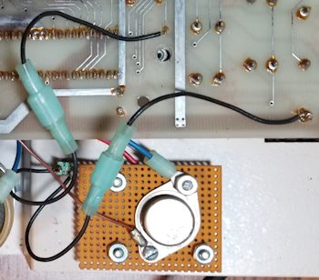
 Here's a nice view of the BREAK/NO BREAK wiring and toggle activation switch. With this MOD, one can disable an accidental softboot caused by pressing the BREAK key on the keyboard. Click image for larger view.
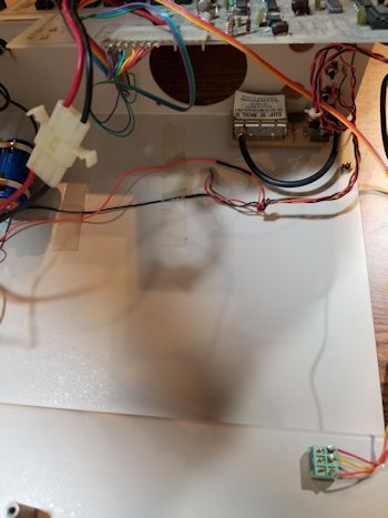
BREAK mod pic2 BREAK mod pic3  Here's the view from the underside mid-board edge conenctor. From this angle one can see the TAPE toggle (bottom right) and to the left of the large circular fan opening, the serial port. (Follow the purple/blue/green wires) Click image for larger view.
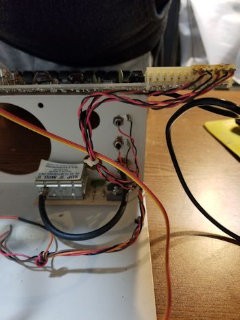
wiring pic2  Pictured is a view of the mod wiring from the underside of the the corner edge connector. From here you can see the SUP-R-MOD RF adapter, video port and cassette ports. Click image for larger view.
wiring pic4 wiring pic5 wiring pic6 wiring pic7 wiring pic8 wiring pic9 More photos (full motherboard, power, etc.) NEXT: I should have most of the schematics, or I can pretty easily plot out the circuits for these mods for support purposes. One would have read articles describing these mods, with schematics, from old magazines like 6502 journal or MICRO, Kilobaud, etc. When I get the chance I will post more info if I discover something useful that is not already out there. Reply |
|
Resources:

Popular Topics and FAQs
Past Issues:
Before we switched over to a blog format, past page archives here:
Vintage Computer Festival East 3.0 June 2006
Commodore B Series Prototypes July 2006
VOLSCAN - The first desktop computer with a GUI? Oct 2006
ROBOTS! - Will Robots Take Over? Nov 2006
Magnavox Mystery - a Computer, or? Jan 2007
The 1973 Williams Paddle Ball Arcade Computer Game Feb 2007
The Sperry UNIVAC 1219 Military Computer May 2007
VCF East 2007 - PET 30th Anniversary June/July 2007
The Electronic Brain August 2007
Community Memory and The People's Computer Company October 2007
Charles Babbage's Calculating Machine December 2007
Vintage Computing - A 1983 Perspective February 2008
Laptops and Portables May 2008
From Giant Brains to Hobby Computers - 1957 to 1977 August 2008
Historic Computer Magazines November 2008
World's Smallest Electronic Brain - Simon (1950) December 2008 - Feb 2009
Free Program Listings Spring 2009
Computer Music Summer 2009
Popular Electronics Jan/Feb 1975 - Altair 8800 Fall 2009
Early Microcomputer Mass Storage Summer 2010
GDM 20D11 display rear

This image was selected at random from the archive. Click image for more photos and files from this set.