 VC Blog | Contact
Sperry UNIVAC 1219 Military Computer
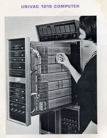
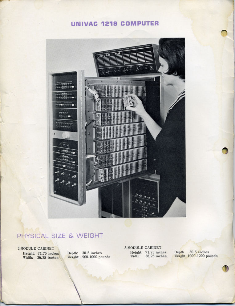
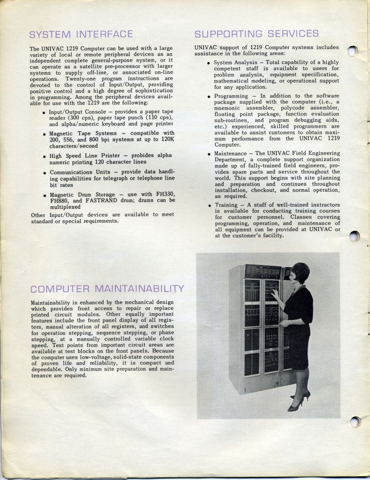
Woman demonstrates insertion of printed circuit modules
Earlier this spring I received the sales brochure and a dual nor gate component from a mid 60's Sperry Univac 1219 Military Computer. Tom Morrison, who sent me these materials operated the 1219 while in the Navy. In addition to the sales brochure he also sent me hand-written notes and the repertoire of instructions from a MK 152 targeting computer.
Tom writes: "..There were hundreds of the cards in rows. ... We did not have any way to run an assembler on the ship. Our main programs were on mylar tape, punched bioctal that we fed through a reader. Later on there were cassette tape loaders. Output was to teletype. (The 1219 was an) 18-bit machine with the ability to double out to 36 bits for more accurate computation. Each instruction took micro seconds. The real-time clock could be turned off and then the machine could be stepped through a phase at a time, also there was the ability to do an instruction one at a time. This was called operational stepping. The 1219 was wire-wrapped. Our ship's ICR (index control register) was miswired - the zero and one bits were reversed. Every time we loaded a program we had to call up certain addresses and change them before we run the program. All of the inputs/outputs were fed through a digital-to-analog box to run the missile system. The designation to a target was then used to make orders for the track radar. When the radar was tracking, missile orders were sent to the missile and launcher. There were gyros on the tracking radar and the master gyro was an input to modify outputs. The pulse frequency for the radar was used to compute range and speed..."
"..Memory was a magnetic core of 128K. There were cards that were just for loading, like ROM. Lower addresses were for interrupt and modifiers. Index control, B register and P register extension allowed addresses different memory stacks. THe I/O was 8 channel with the ability to handle 8 peripherals each. I/O was scanned with the lower channel having the highest priority..." -- Tom Morrison, 2007
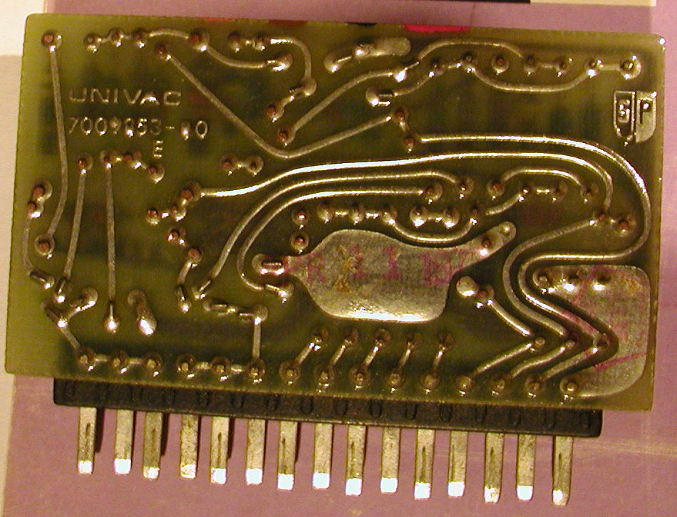
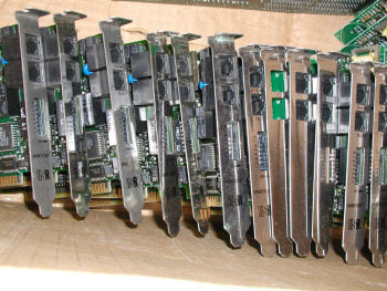
Backside closeup of dual nor gate card from Univac 1219. The woman in the picture above is holding a similar unit
More pics
More pics
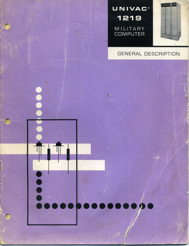
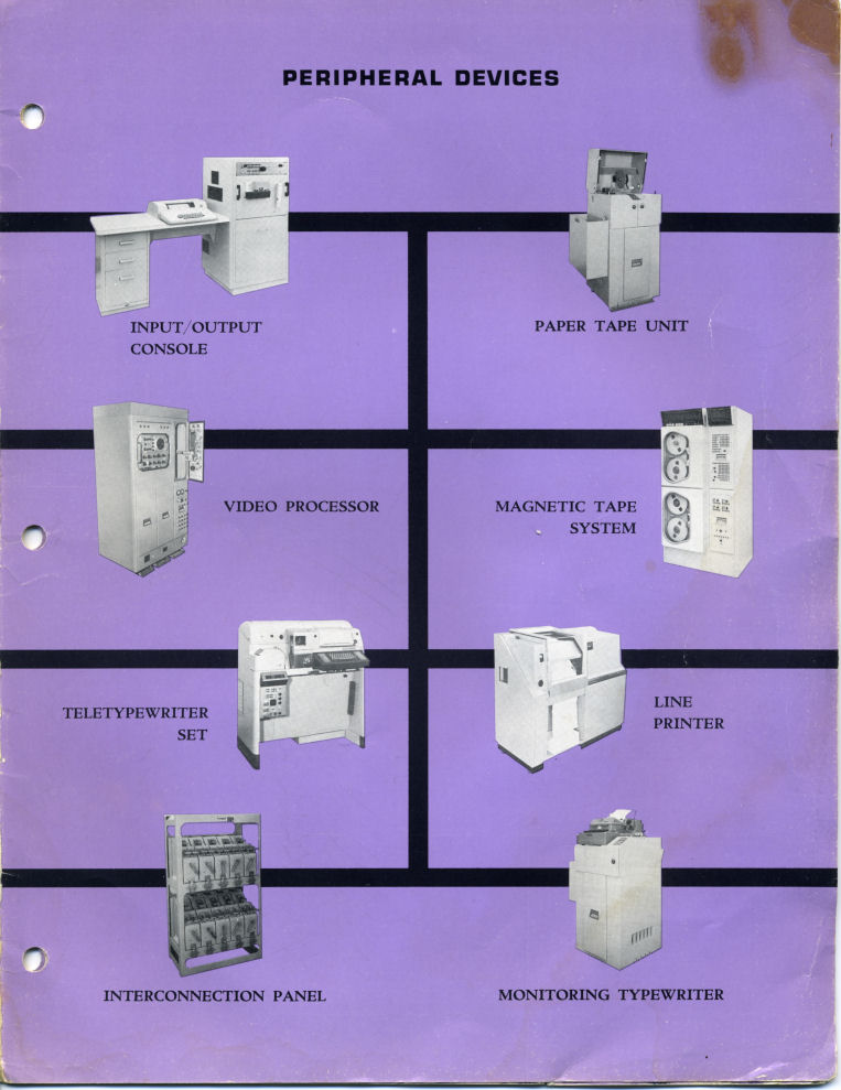
Sperry UNIVAC 1219 Military Computer Sales Brochure
Cover
Inside Cover
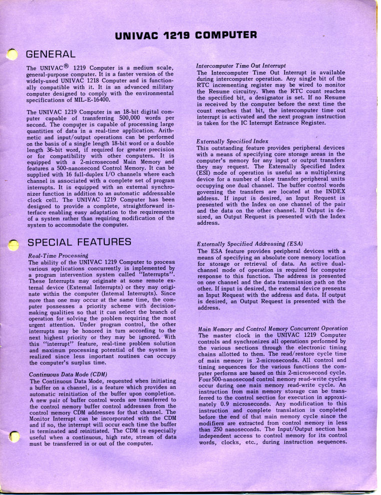
General / Features
System Interface / Support
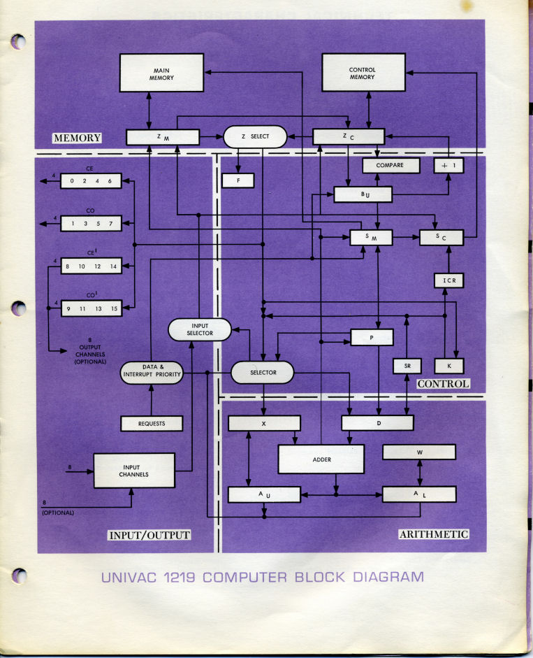
Univac 1219 Computer Block Diagram
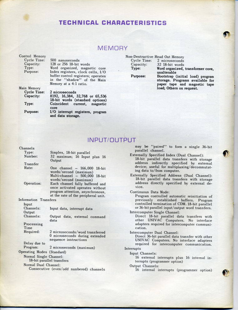
Technical Characteristics
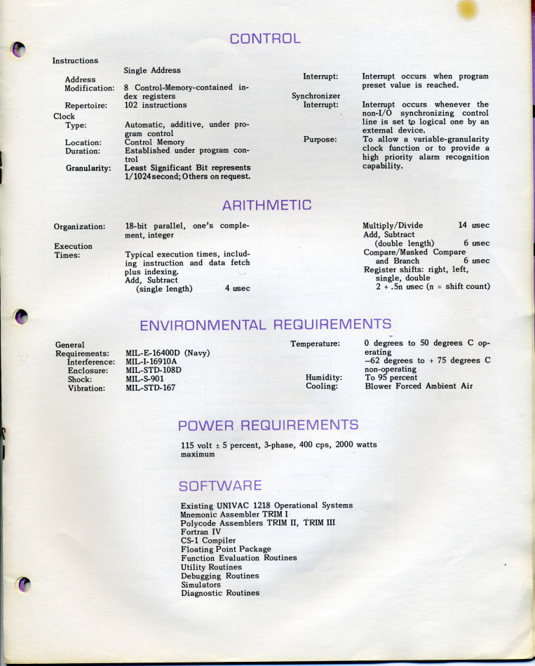
Control / Arithmetic / Power Requirements / Software
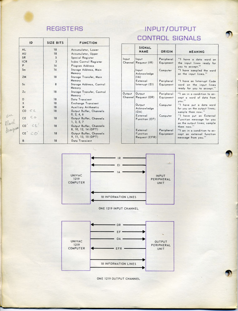
Registers / I-O Control Signals
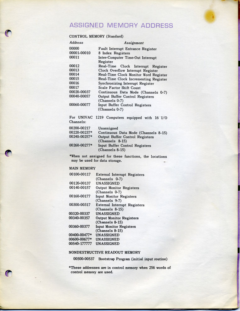
Assigned Memory Addresses
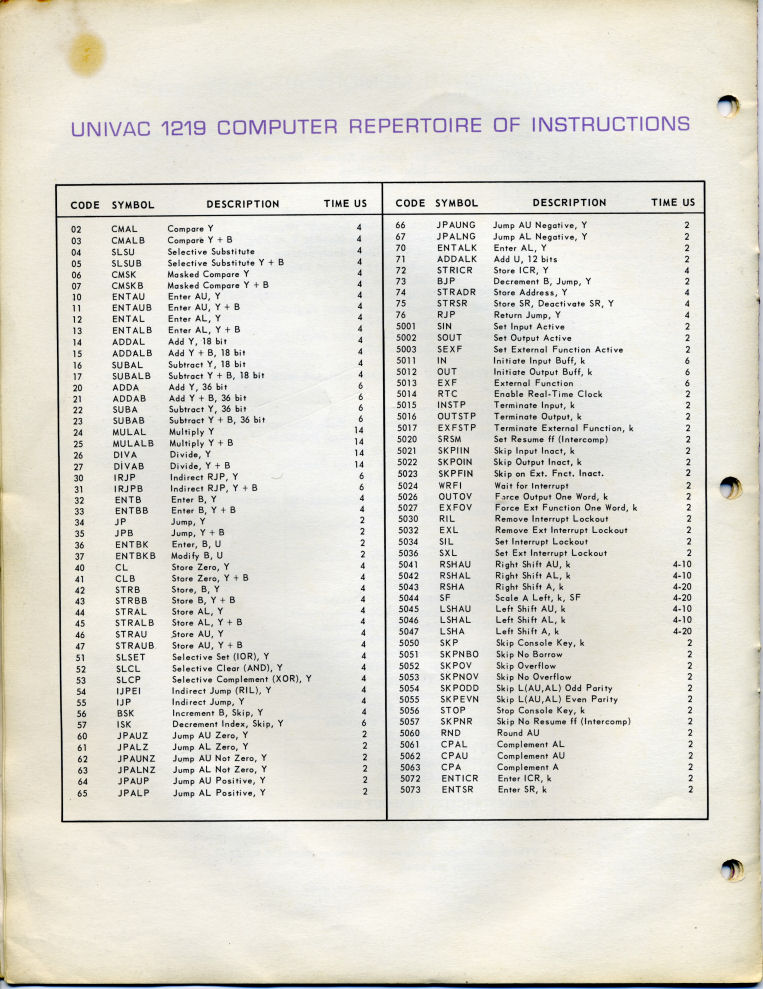
Computer Repertoire of Instructions
Inside Back Cover
Back Cover
Click here to enter your comments.
Commodore Plus/4 Easter Egg
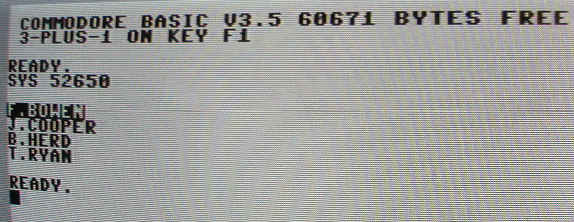
Who's J Cooper?
In a recent conversation on the CBM-Hackers user group, none other than Bil Herd revealed to the group that there is an Easter Egg on the Plus/4 system. ".. John Cooper is/was a very real person, he once threw a fake brick at my head. He did code revolving around the cassette and other stuff, he didn't stay at CBM long after the TED came out, none of us know where he went after that.
Fred Bowen did the Kernel, which would explain why his name is highlighted.
I did the hardware though the reality is the hardware design was really dictated by the chip since it was the closest thing to s single chip computer for it's time. Just add a processor, some rom, some ram, some more decoding, a reset circuit and oh yeah, a keyboard buffer. And a handful of analog circuitry, some RFI filters, a modulator....
The address we used to remember it by, if memory serves, was sys dec($cdab) or in other words we would think of abcd, byte swap it and then go to the decimal equivalent. (we byte swapped automatically those days which meant dialing the last four digits of a phone number could occasionally be a challenge) I still remember the day Terry Ryan described that this was in there and where it was. For the C128 it was something like take half of total memory, round up, then 123,45,6 .."
Bil Herd
Speaking of TED chip systems, here is a link to a hi-res image of a C-116 motherboard. I could not find a good one on the web, so here you go.
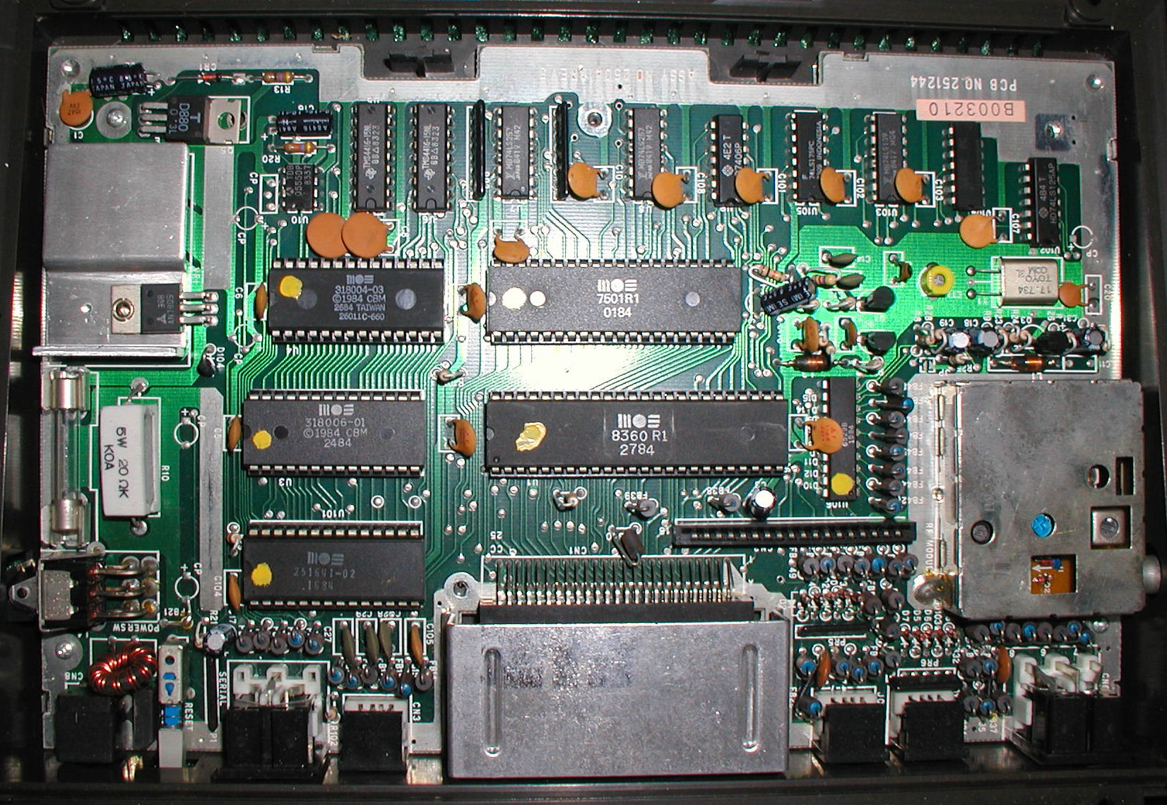
Happy 30th Commodore PET
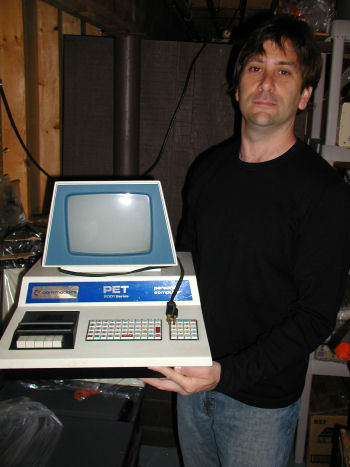
The Commdodore Pet 2001-8
Yes that's a picture of me. Bryan Pope and I worked together to restore this system to full functionality. It needed a little cleaning and a new keyboard. Works great now.
More Comments and pics.
Commodore Prototype on display in June 1977
Making an IBM 1.1 Boot disk
Make a bootable MS DOS 1.1 disk of your very own by following these simple directions.TRS 80 Model 100
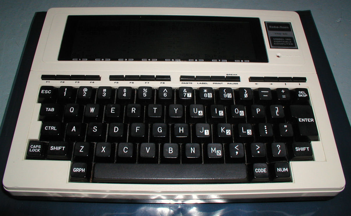
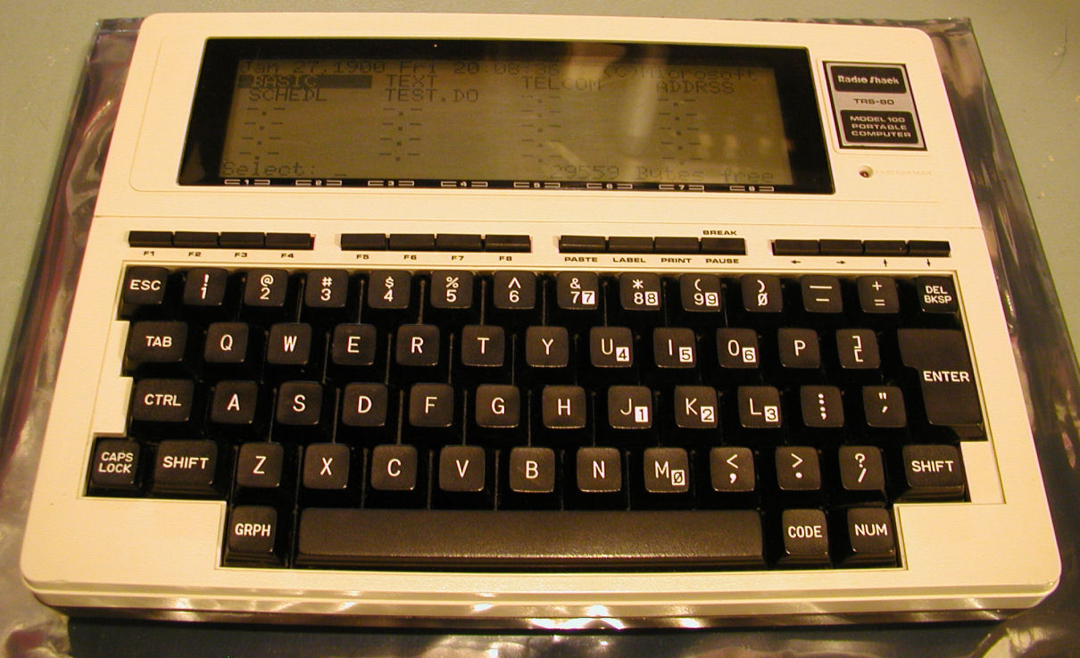
TRS 80 Model 100. Click Image for larger version
Another view
Another view
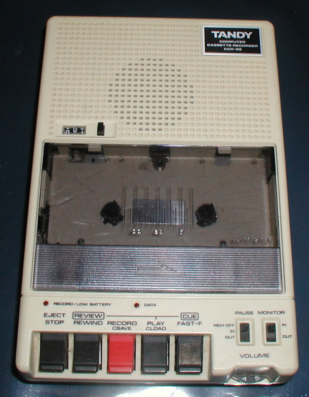
CCR 82 Cassette. Click Image for larger version
I picked this up locally. Complete system in the box, with cassette and disk drive (not pictured). Ran some simple tests and will come back to it later.
Past Issues:
Before we switched over to a blog format, past page archives here:
Vintage Computer Festival East 3.0 June 2006
Commodore B Series Prototypes July 2006
VOLSCAN - The first desktop computer with a GUI? Oct 2006
ROBOTS! - Will Robots Take Over? Nov 2006
Magnavox Mystery - a Computer, or? Jan 2007
The 1973 Williams Paddle Ball Arcade Computer Game Feb 2007
The Sperry UNIVAC 1219 Military Computer May 2007
VCF East 2007 - PET 30th Anniversary June/July 2007
The Electronic Brain August 2007
Community Memory and The People's Computer Company October 2007
Charles Babbage's Calculating Machine December 2007
Vintage Computing - A 1983 Perspective February 2008
Laptops and Portables May 2008
From Giant Brains to Hobby Computers - 1957 to 1977 August 2008
Historic Computer Magazines November 2008
World's Smallest Electronic Brain - Simon (1950) December 2008 - Feb 2009
Free Program Listings Spring 2009
Computer Music Summer 2009
Popular Electronics Jan/Feb 1975 - Altair 8800 Fall 2009
Early Microcomputer Mass Storage Summer 2010
On the Work Bench - May 2007
These are some of the computers and things that I am currently working on, or have recently picked up. Check my Vintage Computer Blog for updates, or post your questions.MITS Altair 8800B
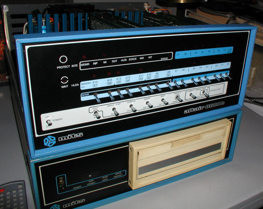
Click Image for larger version
Ahh...Very little restoration was needed for this system. I have learned a lot from the good people at the Altair Computer Club and a lot of reading.
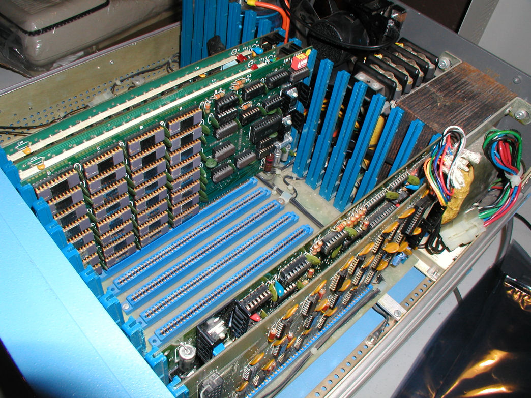
Click Image for larger version
The power supply was performing weakly, so I disconnected the fan from the internal power supply and attached a separate power plug for just the fan to connect to an outlet.
Click Image for larger version
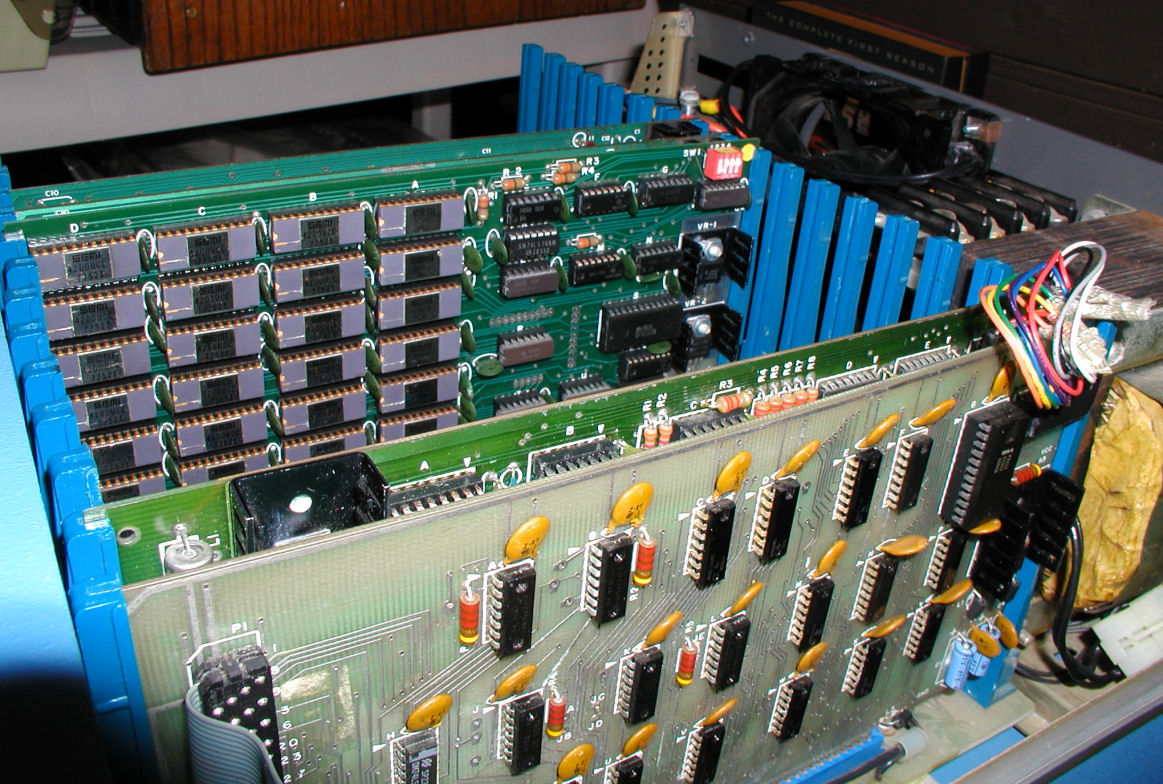
Lastly I moved the three memory cards (total=48K) next to the fan. Using the manual I tested the memory.
Share your thoughts and suggestions here
1977 Morrow Wunderbuss "Thinker Toys" S-100 Motherboard
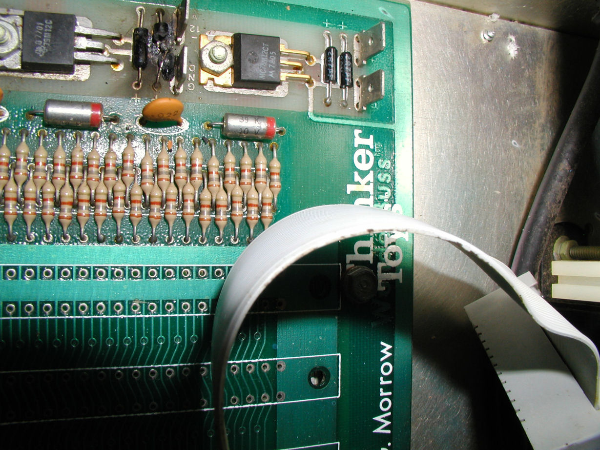
Click Image for larger version
Note the blown electrolytic capacitor at the top of the image. This is a work in progress...The board was installed in an IMSAI 8080 computer configured to use an ASR 33 Teletype. I am very much interested in getting this system up and running with the teletype.
Click here for a progress update / make comment
MITS Altair 680B
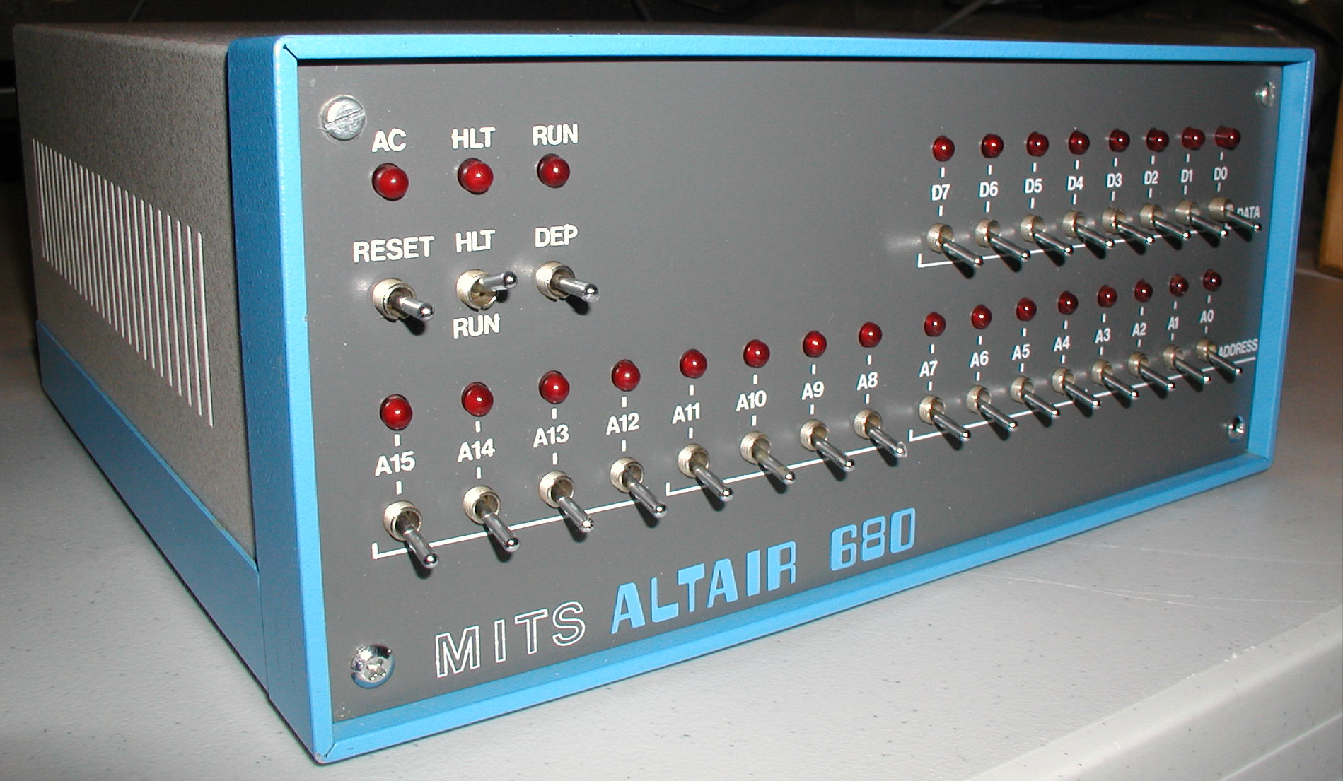
Click Image for larger version
I spent a number of hours working on this system. I reviewed the documentation, tested the memory, and I picked up a ACIA monitor ROM from a kind member of the Altair Computer Club. All seemed to be working, but I was unable to send output through the RS232 port to a display/monitor. I brought the system to the Trenton Computer Festival to meet with other members of my computer club, the Mid Atlantic Retro Computing Hobbyists. Dan Roganti, Brian Applegate, and Brian Pope helped locate and fix a wiring problem (wrong pin connection) and now the system communicates with a terminal, displaying the dot prompt.
More pictures
Comments
Classic Computing Items for Sale:
| CBM Commodore B Series Software (B-128 / CBM 700) | ||
| Superscript II Word Processor | $29.99 | |
| Superbase Database Manager | $29.99 | |
| Commodore Advanced Business Systems (CABS) Acccounting Suite: Accounts Payable, Order Entry, Accounts Receivable, General Ledger (4 binders) | $29.99 | |
| More CBM Commodore Items | ||
| Commodore B-128/700 Programmer's Reference Guide - Protecto - Everything you need to know about the B line! | SOLD OUT | |
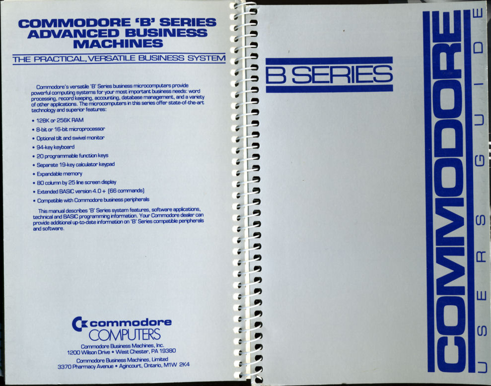
| B Series Commodore Users Guide - View Image | $39.99 | |
| Commodore Users Guide Series 8000 | $39.99 | |
| Commodore BASIC Users Refence Manual Version 4.0 | SOLD OUT | |
| Commodore CBM Expansion Memory Board 64K Expansion Kit for PET 8032 (NOS) | SOLD OUT | |
| Commodore PET Keyboard (NOS) for 2001 -N, 3000, 4000 Series | SOLD OUT | |
| Other Commodore CBM Power supplies, software, parts, etc. | Contact Me | |
| Tandy Items | ||
| Aeoromp Double Density Controller for TRS 80 Model 1 Expansion Unit (NOS)- details | SOLD OUT | |
| Model III / Model 4 (non-gate array only) RS-232 KITS details | SOLD OUT | |
| Model III / Model 4 (non-gate array only) RS-232 boards only | SOLD OUT | |
| Model III Aerocomp Diskdrive controller | $39.99 (free US Ship) | |
| Looking for Something Else? | ||
| Please check here first with special requests for Commodore, IBM, Tandy, Atari, TI, Apple computers, parts, components, and software. I have systems plus zounds of miscellaneous items for sale or trade. | ||
History of Commodore Computers Poster $19.99
For more information about the C Prompt found at the top of each page, click here.
All photography on this web site is � VintageComputer.net/Bill Degnan and cannot be reproduced without permission.
This web site has two purposes.
For years I have been making research notes while in the process of restoring classic computer systems, and I also like to record tidbits of information that I think might be useful in the future. This web site is a way to share this information for research purposes. I will also post restoration project reports, project summaries, users guides, tutorials, and items wanted. I invite anyone who wishes to contribute their comments to the VC Blog to do so. My goal is to publish new content in the field of classic computing.
The second purpose of this web site is to sell off my duplicate items. Unless otherwise stated, all items for sale are in working order. If you wish to post items for sale on the VC Blog, please indicate clearly the operational status of the item(s).