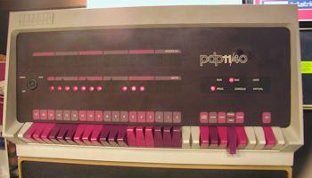
PDP 11/40 72 inch cabinet model
SHARE |
|
  PDP 11/40 72 inch cabinet model
 |
by Bill Degnan - 04/06/2015 21:52 |
|
For lack of a better name, I will refer to this PDP 11/40 as the "full height" or 72" cage system to differentiate it from the others I am working on. The PDP 11/40 front panel and card cage chassis is located at the top of the 72" cabinet. This photo was taken before the unit was cleaned up. Click image for larger view.
Note the H and G modules of a core memory system. These cards are from the top chassis. Click image for larger view.
This photo is of the bottom chassis cards. Click image for larger view.
More Pictures Reply |
|
  Card Inventory
 |
by Bill Degnan - 08/23/2015 21:09 |
|
This is essentially the same as the "industrial 11" without the special front panel. The CPU is on the top rungs of the cabinet, not sure why they did that. This system has 128K Core RAM.
CPU / main cabinet (top) 1: empty 2: M7238 3: M7232 (1-4), M7237 (5), M787 (6) 4: M7231 5: M7233 6: M7235 7: M7234 8: M7236 9/11: M981 (1-2) (10 n/a gap) 11: M8294 (3-6) 12: M7959 (1-2) 13-15: G236 H224C G116 16-18: G236 H224C G116 19/21: M920 (1-2) (20 n/a gap) 19: M8294 (3-6) 21: M920 22: M7259 23-25: G236 H224C G116 26-28: G236 H224C G116 29/31: M920 (1-2) (30 N/A GAP) 31: M7911 (3-6) 32: M7912 33: M7821 (2) M796 (3) M105 (4) M930 (5-6) BUS TERMINATOR 34: M795 (3-6) ------------ EXPANSION CHASSIS (ON BOTTOM) 1: GC (4) 2: GC (4) 3: -- 4: -- 5: GC (4) 6: GC (4) 7: M8291 8: GC (4) 9/11: M920 (1-2) (10 N/A GAP) 11: M7297 (3-4), M7296 (5-6) 12: M7295 13: M7294 14: M5904 (3-4) 15: M5904 (3-4) 16: M5904 (3-4) 17: GC (4) 18: GC (4) 19: GC (4) Reply |
|
  re-assembly and power
 |
by Bill Degnan - 05/12/2016 13:50 |
|
There were two voltage regulators present in the system when I got it. The missing three spaces were empty. From the dust, it would appear these slots were empty for a long time. The h754 and h744 pictured here are good. The missing regulators indicate that this system was scrounged for parts. Click image for larger view.
I have no experience with the h7420a (note the extra "0"). The controller board and configuration of the h7420a differs from the h742a, but I believe they are functionally the same. For now I will go with this assumption anyway. Click image for larger view.
Based on this diagram, I assume I need to find a working h745 and two more h744 voltage regulators to properly power up a system full of core memory. Click image for larger view.
 At present, the system shows a AC LO DC LO condition. Click image for larger view.
Connor Krukowski stopped by to work most of the day last week to help clean and prep the system for testing. He helped sort of the voltage regulators, test the power supplies, label and organize the parts, etc. Connor performed electrical tests. Since then I repeated his tests and compared the readings with the working 11/40 nearby. There is a lot of work left. We have not tracked down all of the faults power or otherwise. I have returned all of the original cards to their original slots. I have not yet tested the front panel itself, nor the cpu or RAM. A bad CPU could cause a DC LO AC LO condition in addition to any issues with the power supply. Although I need at least one h745, I might be able to get away with only the one h744 by removing all but the CPU cards, for testing purposes at least. Next: Find and test an h745 and one-three h744's. Reply |
|
Resources:

Popular Topics and FAQs
Past Issues:
Before we switched over to a blog format, past page archives here:
Vintage Computer Festival East 3.0 June 2006
Commodore B Series Prototypes July 2006
VOLSCAN - The first desktop computer with a GUI? Oct 2006
ROBOTS! - Will Robots Take Over? Nov 2006
Magnavox Mystery - a Computer, or? Jan 2007
The 1973 Williams Paddle Ball Arcade Computer Game Feb 2007
The Sperry UNIVAC 1219 Military Computer May 2007
VCF East 2007 - PET 30th Anniversary June/July 2007
The Electronic Brain August 2007
Community Memory and The People's Computer Company October 2007
Charles Babbage's Calculating Machine December 2007
Vintage Computing - A 1983 Perspective February 2008
Laptops and Portables May 2008
From Giant Brains to Hobby Computers - 1957 to 1977 August 2008
Historic Computer Magazines November 2008
World's Smallest Electronic Brain - Simon (1950) December 2008 - Feb 2009
Free Program Listings Spring 2009
Computer Music Summer 2009
Popular Electronics Jan/Feb 1975 - Altair 8800 Fall 2009
Early Microcomputer Mass Storage Summer 2010
tele graphic Tele graphic front

This image was selected at random from the archive. Click image for more photos and files from this set.