Digital Equipment Corporation PDP-8
SHARE |
|
 Digital Equipment Corporation PDP-8
 |
by Bill Degnan - 07/04/2023 18:59 |
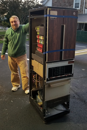 Drew helping wheel our new DEC PDP-8 computer, donated to Kennett Classic museum in late October 2022. I drove the computer from Chicago a few weeks after VCF MW.
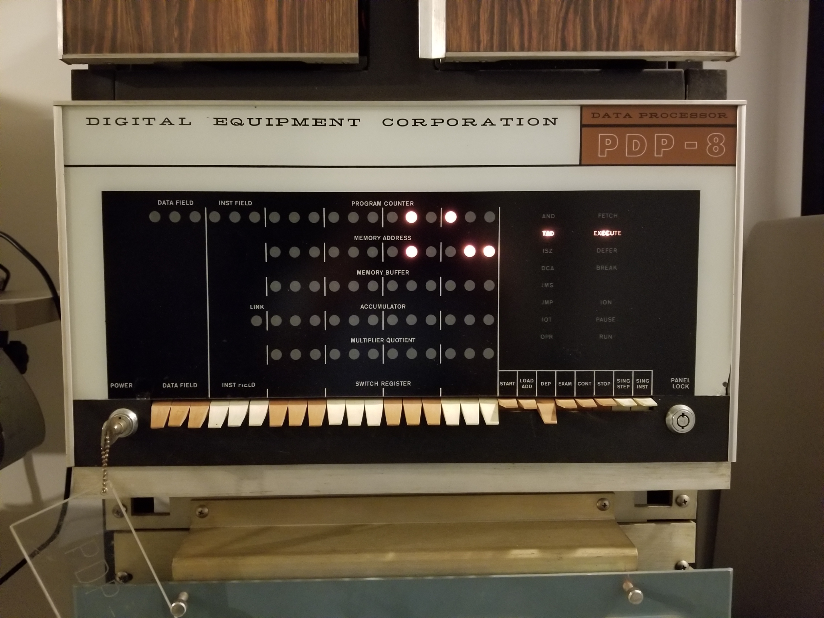 Front panel view, DEC PDP-8 computer
This is the rack model acquired in late fall 2022. The system can run the "chase the lights" program indicating a minimum CPU function. Powering off and then on again, the system retains the values of the chase the lights program and will re-run again. NEXT: Document cards installed, detailed pictures and testing with a Teletype ASR 33. Just so you know, I have powered up this system 25 times and worked with the front panel, but I wanted to clear a good block of time to restoration, kind of saving this for the right month or two to really get into it properly. Dave Gesswein came by to help do a surface level inspection of the computer and he felt it was in pretty good shape. Reply |
|
 PDP-8 Testing
 |
by Bill Degnan - 08/16/2023 23:48 |
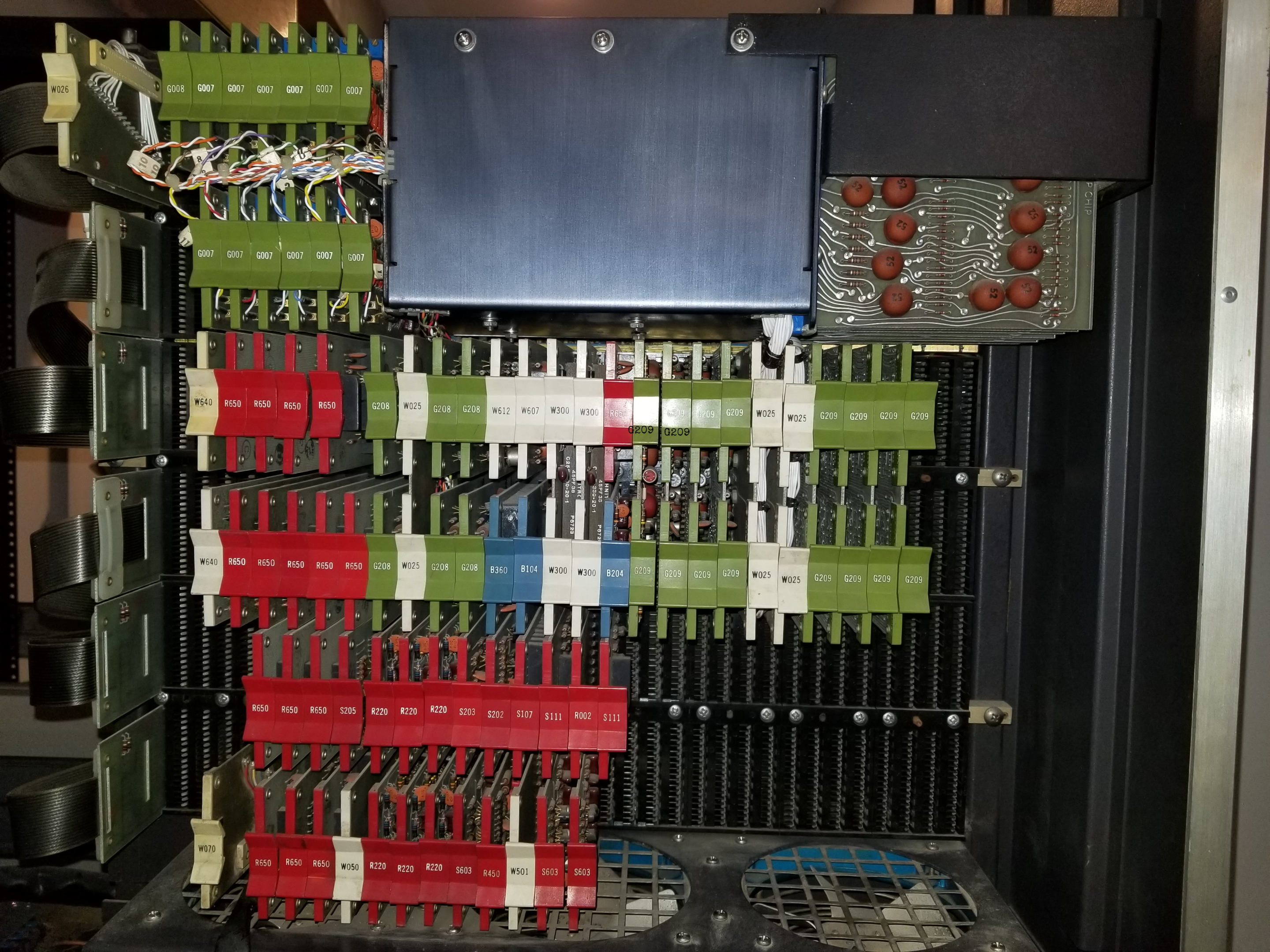 Photo of flipchips that make up the the memory side of the backplane.
More Photos NEXT: Record specific test results to track down the flip chip (or two or three) that have faults, preventing RAM from being correctly saved. I think the core memory itself is OK. Reply |
|
|
Flip Chip Boards Replaced |
by Bill Degnan - 06/29/2024 23:13 |
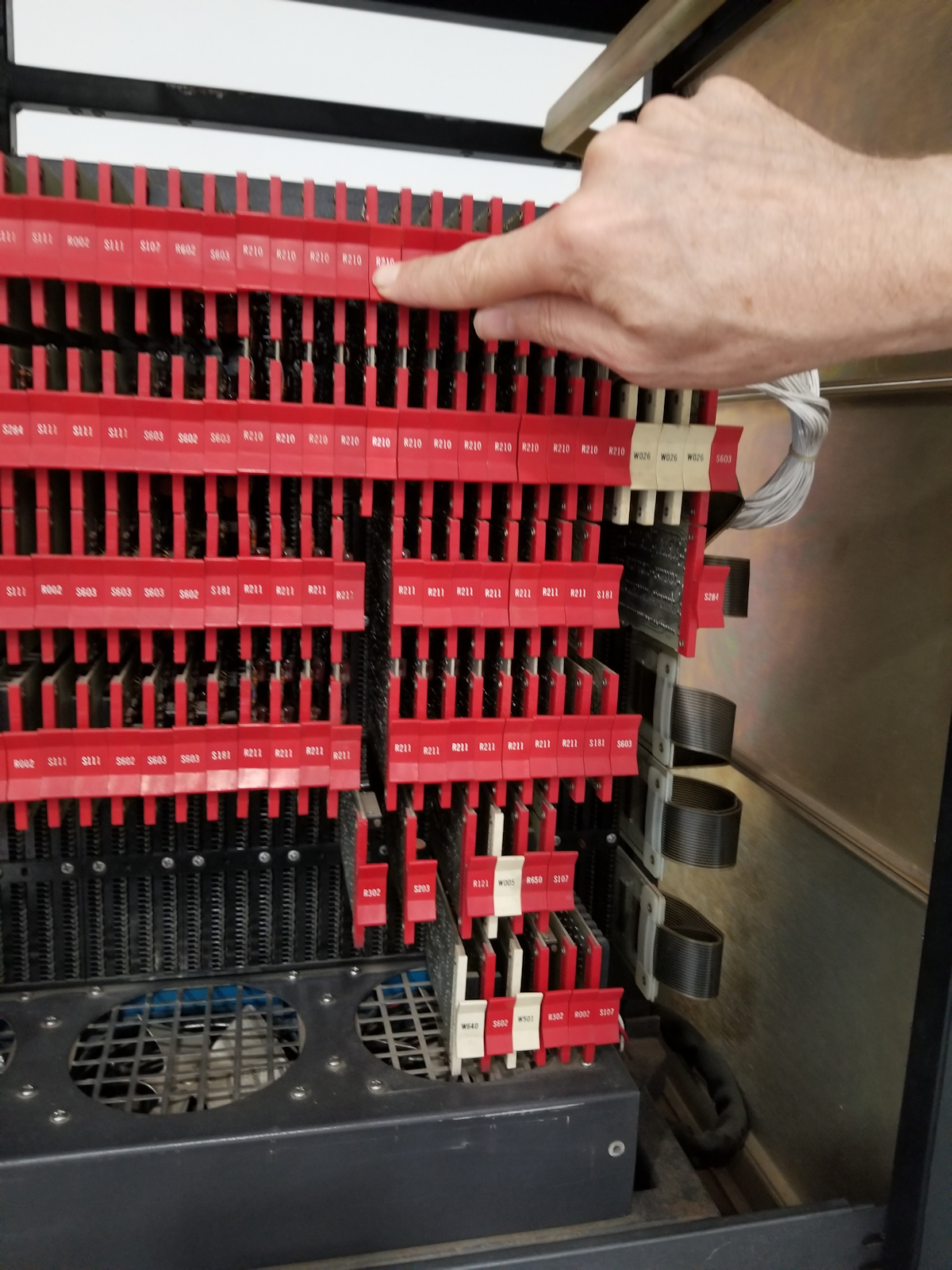 Bit accumulator 7 - R210 was found to be faulty. Note that the R210 in the photo is not part of the memory buffer row, so one should start counting 2nd from the right.
When memory buffer 8 was set memory buffer 7 was also being set. Docs indicated that we should test where the switch register is transferred to the accumulator. Dave pulled the R450 clock generator (on memory console side) and put in his 9600b custom card, and his RS232 converter card, to hook up the PDP8 to his laptop for further testing. Dave downloaded DEC-08-LHAA-D and toggled in teh HELP loaded from 027: 6031 5027 6036 7450 5027 7012 7010 3007 2036 5027 Run & Send file. 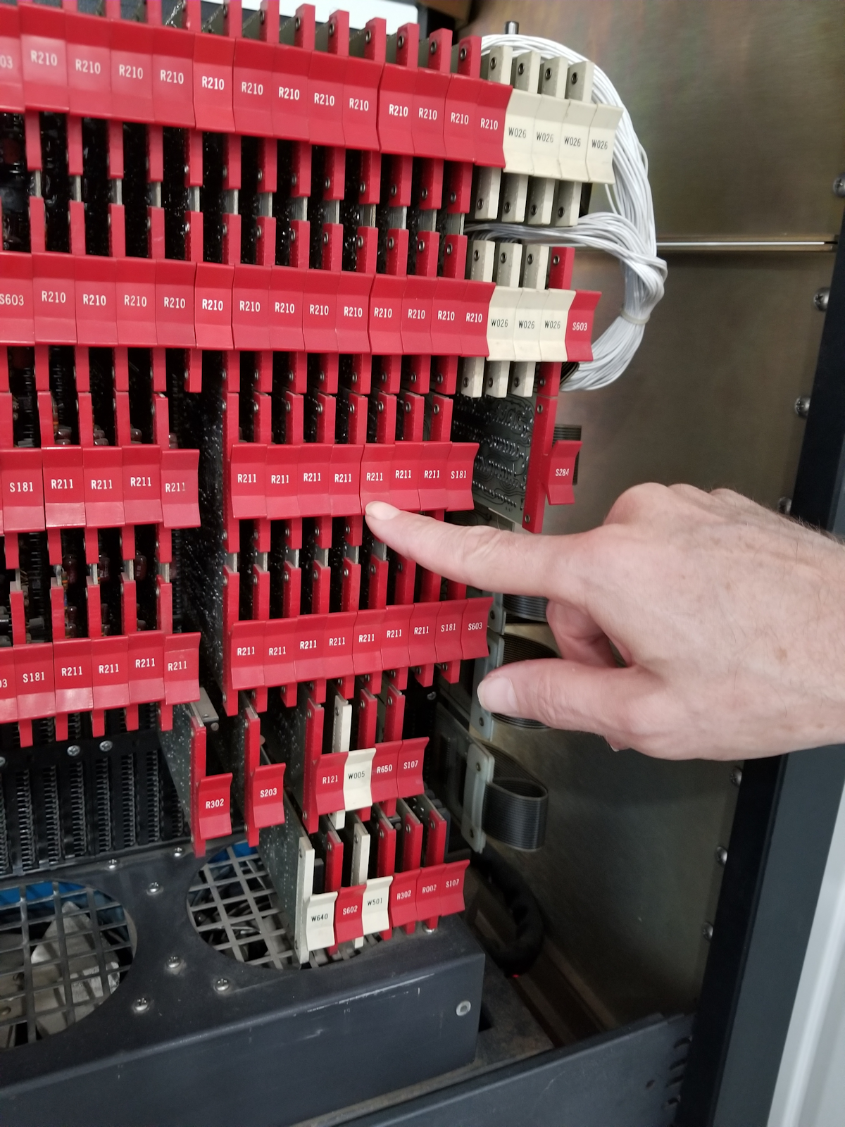 Memory buffer bit 2 fault found, and thus cannot load HELP loader.
Next Dave ran the RIM and BIN loader. Sent tape for diagnostic. Put system to 7756 to start the RIM loader. Next Dave loaded the HELP loader and examined from 27 to confirm it was stored correctly. He RAN the program from 27 and the program failed. Next Dave tied running the RIM loader manually from 7756. When one runs this program it will stay running. So when you send tape it will act on it (watch the accumulator) and hit stop when it appears to be done. Next we loaded MAINDEC-801-1-PM loaded at 200. We put all switch registers up (all 7's) and Ran the program. It should stop at 201 with ACC = 0, 206 with ACC 0. Next Dave toggled in the "Group 1 Micro Instruction" test program from the toggle-in programs hand-written sheet. This test passed. Dave mentioned the BSW does not work on original model PDP-8's. Next, toggled-in test "Operate Instructions" - OK. Toggled in Group 2 Micro Instruction - passed. 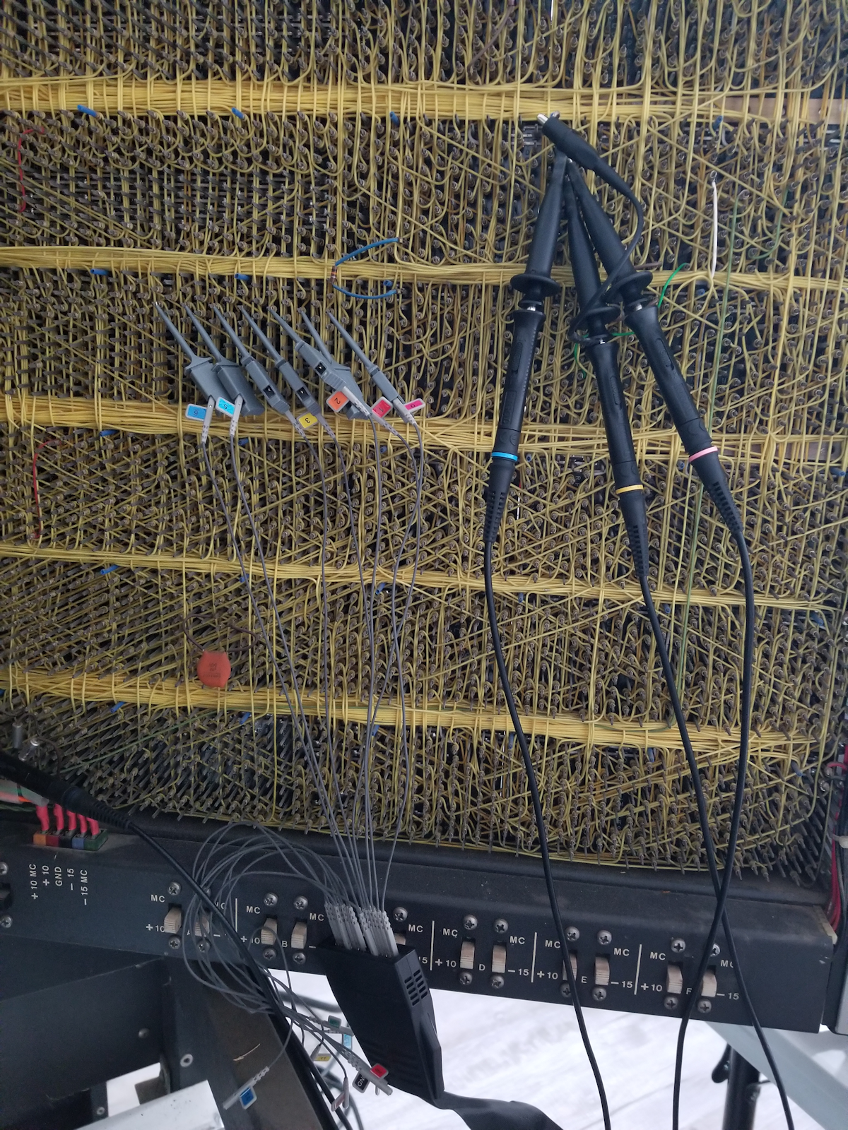 Fetch->Defer->Execute (FDE) testing
check to see if the machine is going through all 3 cycles. To do se we set up a probe PB25. After probling Dave found that the program works. Dave said intermittant issues, perhaps a timing issue. Dave found that the R602 was not FDE-ing and we replaced P28 Start PC 0041 TAD Fetch MA 0040 MB 1410 A 0000 CONT PC 0041 TAD DEFER MA 0010 MB 4002 A 0000 CONT PC OO41 TAD EXECUTE MA 4002 MB 5555 A 5555 Still had issues. Memory corrupting randomly, setting to all ones when reading or writing. Could be write back does not occur. Suspicious that read is occuring but the write back is not, setting an address to all 111's. So next we tried the toggle-in echo program. failed. Memory corrupted. Wondering - could certain instructions trigger failure? Final thought JMP to increment accumulator is OK. JMP and IOT seems to be causing memory to go all 111's intermittantly. IOT is "talking to a peripheral" so as long as the program does not attempt an IOT it appears to be less likely to corrupt the memory location being read to be executed. Next - Do we see this corruption in other programs? Run a memory test to confirm that no errors occur, as this program does not attempt an IOT. What Else?  Test all cards' forward voltage of all diodes" to 5.5 -> 6V. Transistors - emitter junctions .6, .8 drop when leader are in the right direction. You can use a diode tester for both diodes and transitiors.
It's likely there are numerous faulty or marginal diodes and maybe some transitors that need to be replaced. Worst case, we'll improve the electrical state of the computer and perhaps fix the intermittant memory issues with a shotgun approach of going through all diodes on every FlipChip board. 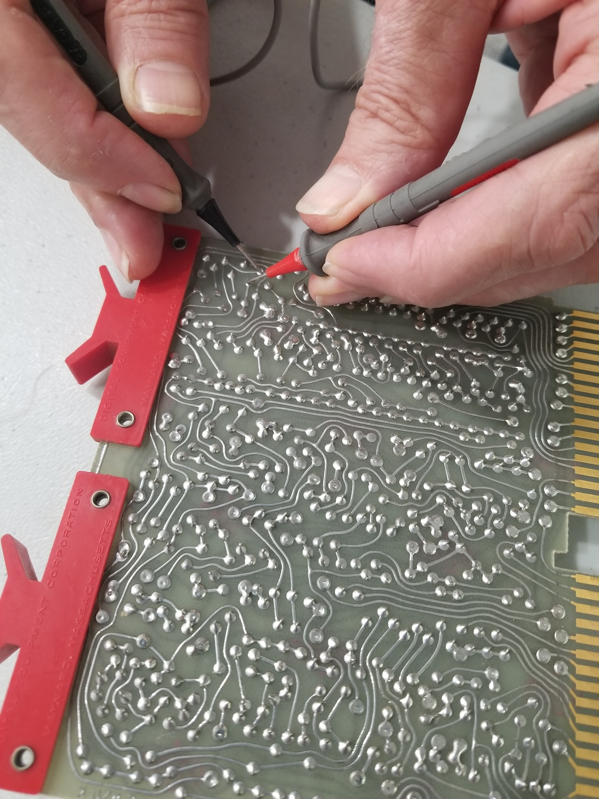 Backside of the same flipchip logic card.
Reviewed this page https://homepage.cs.uiow...pdp8/man/registers.html Reply |
|
Resources:

Popular Topics and FAQs
Past Issues:
Before we switched over to a blog format, past page archives here:
Vintage Computer Festival East 3.0 June 2006
Commodore B Series Prototypes July 2006
VOLSCAN - The first desktop computer with a GUI? Oct 2006
ROBOTS! - Will Robots Take Over? Nov 2006
Magnavox Mystery - a Computer, or? Jan 2007
The 1973 Williams Paddle Ball Arcade Computer Game Feb 2007
The Sperry UNIVAC 1219 Military Computer May 2007
VCF East 2007 - PET 30th Anniversary June/July 2007
The Electronic Brain August 2007
Community Memory and The People's Computer Company October 2007
Charles Babbage's Calculating Machine December 2007
Vintage Computing - A 1983 Perspective February 2008
Laptops and Portables May 2008
From Giant Brains to Hobby Computers - 1957 to 1977 August 2008
Historic Computer Magazines November 2008
World's Smallest Electronic Brain - Simon (1950) December 2008 - Feb 2009
Free Program Listings Spring 2009
Computer Music Summer 2009
Popular Electronics Jan/Feb 1975 - Altair 8800 Fall 2009
Early Microcomputer Mass Storage Summer 2010
DEXTIR 1961 ESSO
This image was selected at random from the archive. Click image for more photos and files from this set.