Slugging it through XXDP Diagnostics
SHARE |
|
 Slugging it through XXDP Diagnostics
 |
by Bill Degnan - 07/06/2016 11:18 |
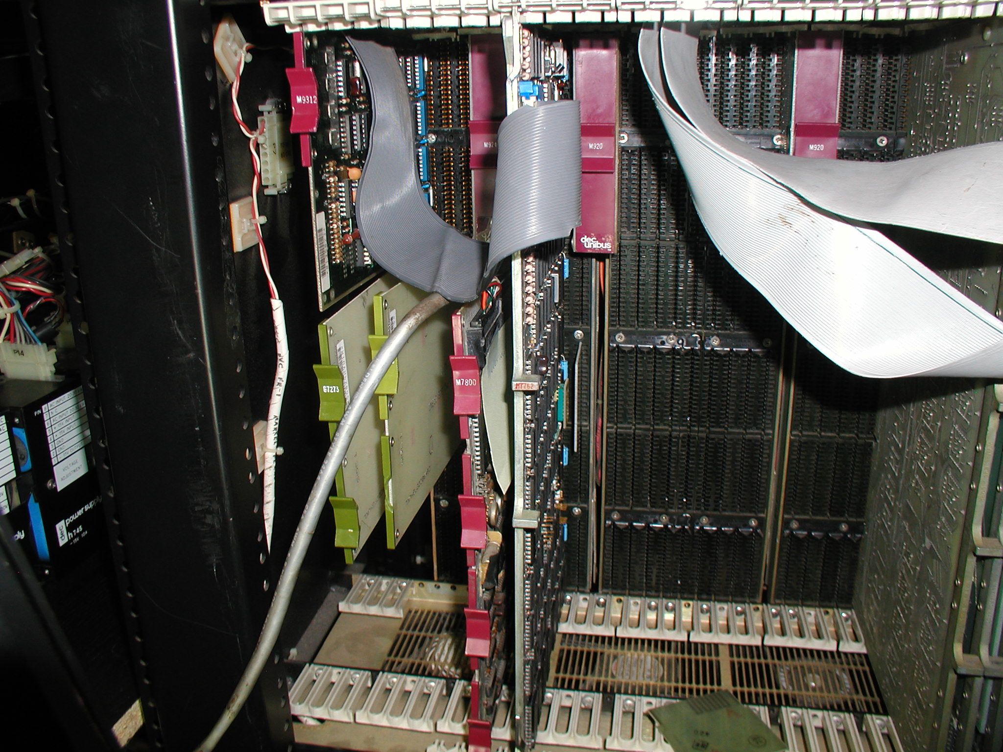
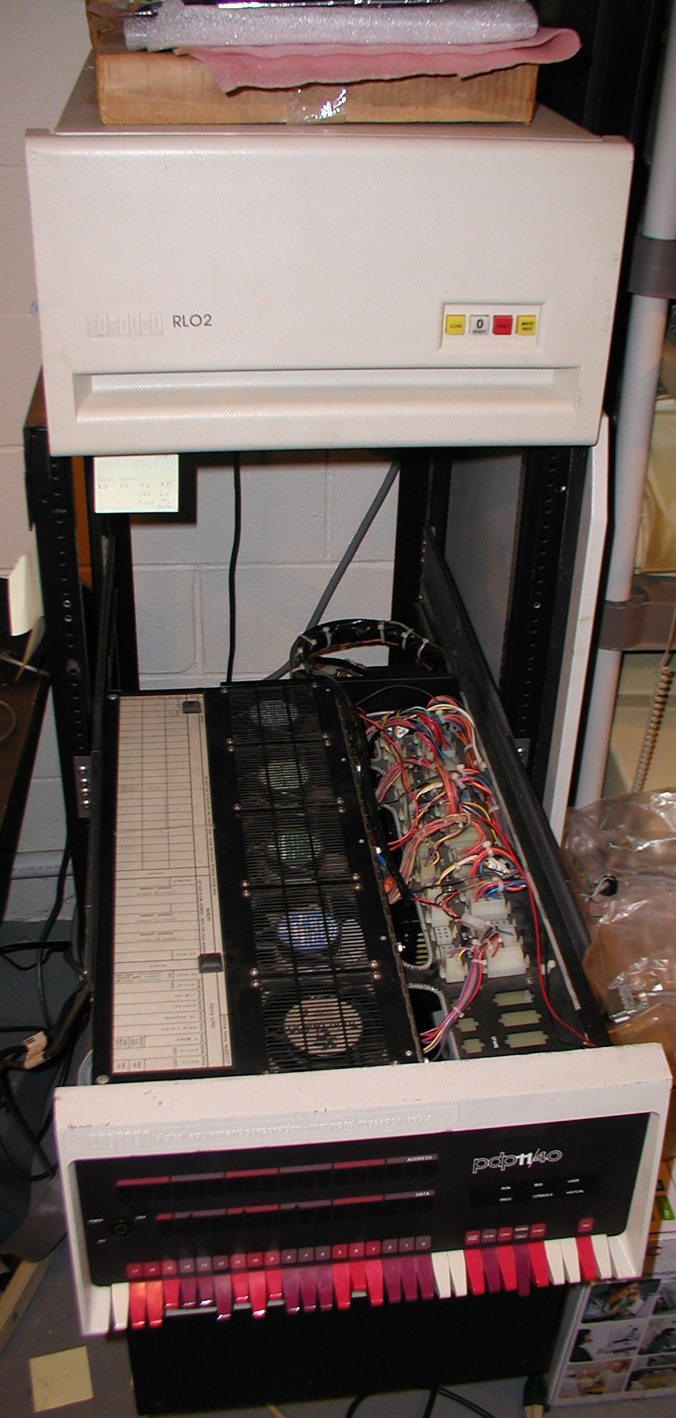 PDP 11/40 in chassis with rack arms extended. RL02 sitting on top of rack. Click image for larger view.
Found at lot here, but not ZRLG or ZRLH http://www.retrocmp.com/...11-diagnostics-database http://www.retrocmp.com/...ase///devices/RL02.html so, I am going to try the maindec-11-dzrla-a-pb1 and maindec-11-dzrla-a-pb2 - and I see that ak-e038b-mc and ak-e039b-mc I think replaced the first two. * * * * * * UPDATE - found page 2-40 RL01-RL02 user guide to confirm CZRLAAO and CZRLBAO are correct. "..These diagnostics can be run free-standing under the Diagnostic Supervisor, manually under XXDP, chainable under XXDP (except CZRLFAO which requires manual intervention), or under manufacturing checkout environments such as SLIDE or ACT-II. A new diagnostic package is available to test either an RLOI or an RL02 unit. The kit numbers are listed in Table 2-6 and the contents of the tests are shown in Table 2-7. ." RLll Diagnostic Kit Numbers ZJ283-RB - Documentation and paper tape AC-FIIIA-MC CZRLGAO Controller Test #1 Documentation AK-FI08A-MC Paper tape #1 AK-FI09A-MC Paper tape #2 AC-FI15A-MC CZRLHAO Controller Test #2 Documentation AK-FI12A-MC Paper tape #1 AK-Fl13A-MC Paper tape #2 Reply |
|
 Finding a Good Test Program
 |
by Bill Degnan - 07/07/2016 09:52 |
|
ZRLG - loaded and promptly died. Need the docs.
Reply |
|
|
RL11 Controllers OK |
by Bill Degnan - 07/21/2016 01:45 |
|
I sent three RL11 controlelrs (M7762), my cables and the diskpack to Ray Fantini to test. They all checked out.
Reply |
|
|
Preparing a Second DL11 for XXDP |
by Bill Degnan - 11/23/2016 11:14 |
|
Repeated attempts switching things around, testing, re-testing...but I can't get the CPU to talk to the RL11 controller. I believe this is a DMA issue. Up to this point I had been loading in one routine at a time using PDPGUI. Some success, used this method to learn my system was expecting a KJ11 (M737), which fortunately I had. Since then I verified that my CPU cards are correctly jumpered for what I have installed in the backplane. Per conversations on CCTECH I believe I have the correct cards and enough working RAM to operate RT-11.
The consensus opinion for my case is to get serious with XXDP diagnotics. To that end I can install a 2nd DL11 and use this as the interface for a TU58 emulator from which to install XXDP into the PDP 11. The TU58 is a DEC tape drive, and many before me used this drive to download both XXDP and RT-11 "serially" when no other means worked. System wired for KW11-L? I never thought to check the CPU backplane for things like grant continuity and to see if my system was used with a KW11-L in the past. This CPU set came from a different system and it's possible that the original system used one. To learn the truth I need to check for a missing jumper in slot 3 of the CPU backplane. F03R2 and F03V2. I actually do have a KW11-L (M787) from the Industrial 11. I have attempted to use it with this system but it causes CPU faults and I can't do much other than toggle memory using the front panel. Simple CPU programs fail, and I can't boot using M9312. (I actually tried 2 of these cards, same result) I thus assumed I do not have a CPU backplane wired for a KW11-L, but I never ruled out the possibility that the problem is with the M787 card, a fault in the card. I have 0 experience with altering or testing backplane jumpers, but I will try. I have always used an extender card instead and probed signals form the extension card as a cheat. It seems like the NPG is OK AFAICT, but I did not check slot 9 which others have reported sometimes gets altered for custom reasons. It does not seem to matter whether I have a grant card in slot 9 (?). Will come back to this later. I would not mind getting something like Guy S's modern UNIBUS Tester "UA11" to test with. As of this writing there are no assembled units available. So, the next thing is to get a 2nd DL11 (M7856) wired to address 776500 so I can emulate a TU58. 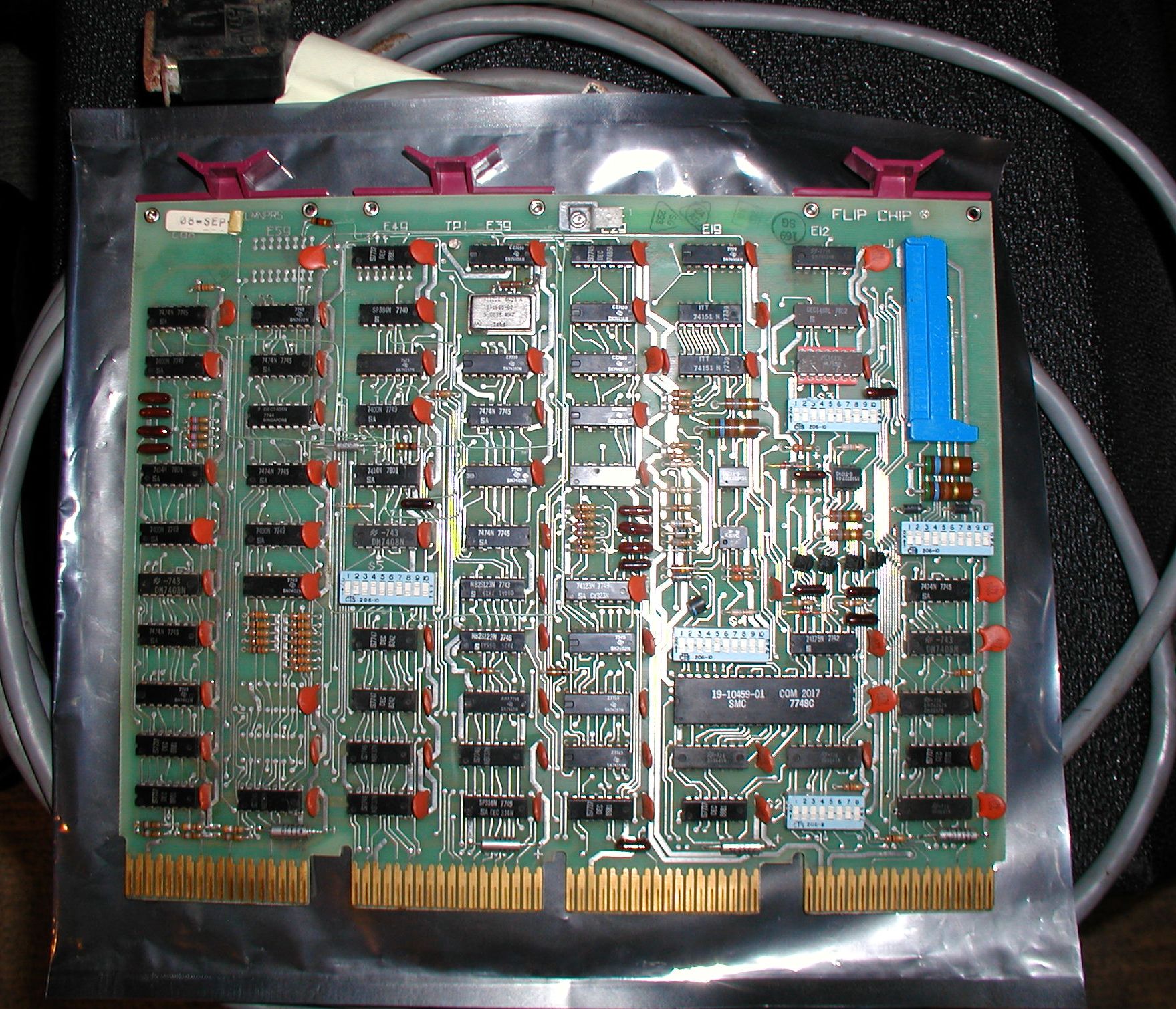 UNIBUS DL11-W (M7856) jumpered to serve as the serial connector for a TU58. The card is sitting on a nice long shielded DEC serial cable. Click link for larger picture.
Configuring a DL11-W (M7856) as the 2nd serial device (for TU58): First one needs to set the jumpers on the card. I read the manual but I could not confidentially determine the correct settings. In these situations the web is your friend. An excellent and much appreciated page that explains how to jumper a DL11-W (M7856) to act as the interface for a TU58 is found here (with better photo than the above): http://www.pdp-11.nl/peripherals /comm/interface/dl11-w/dl11w-info.html Next, I need to install a the TU58 bootstrap ROM into my M9312 card. The command is DD. I have a 2nd DEC serial card to connect from the M7856 to the TU58 emulator device (PC serial port). Reply |
|
|
Setting up the TU56 Emulator |
by Bill Degnan - 11/24/2016 20:05 |
|
I learned from the VCFED forum that there is a program called tu58ew (or em) that can be run from a DOS PC command line. I have a windows 2000 machine nearby so that's what I will use. I will have to use a separate PC for the TU58 for now, but hopefully I can use one PC and two serial ports in the future.
Here is where you get Don's emulator: http://ak6dn.dyndns.org/PDP-11/TU58/ From other sources I found this to be suggested use of the emulator XXDP: tu58em -v -d -p 1 -s 9600 -r 11xxdp.dsk also why not go for a little RT11 tu58em -p 3 -s 38400 -r boot.dsk -i rt11.dsk Reply |
|
|
M9312 Config Problem? |
by Bill Degnan - 11/27/2016 10:42 |
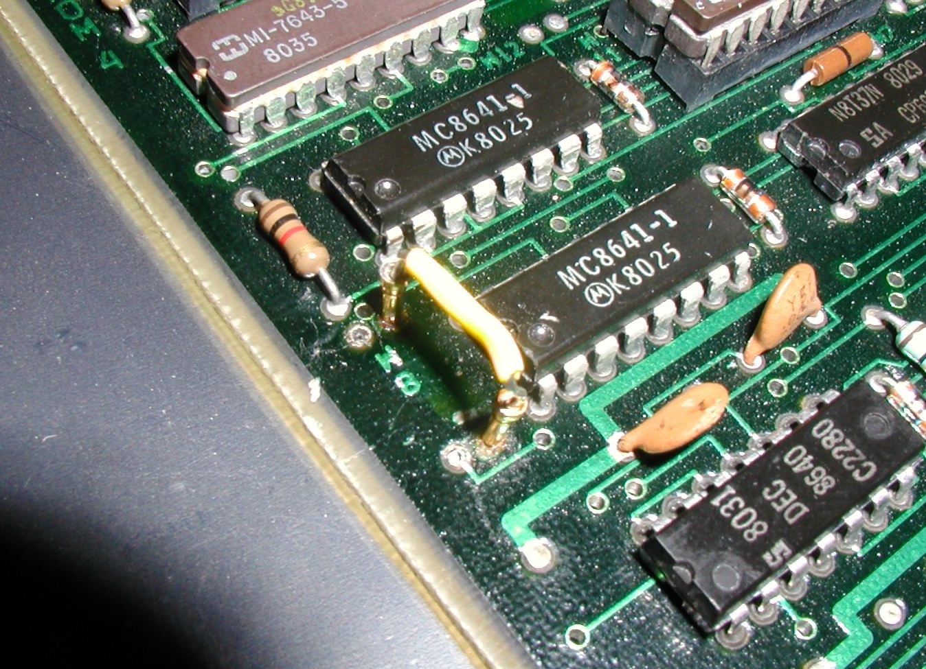 Closeup of the configuration jumper shunt I installed in position W8, so I could switch without re-soldering. Click image for larger view.
The TU58 emulator is not getting the proper handshake from the PDP11 M7856 (DL11-W). Also, the boot ROM bombs when I attempt to run it. Made me think maybe there is an issue with the configuration of my M9312, or at least it's worth a look. I took more photos of the jumpers installed in my M9312 here and shared with CCTECH mailing list. Here is the page from the manual that describes jumpers per UNIBUS system type. It says to close W8, but in other places it says leave it open, specifically if one wants to run the CONSOLE or DIAG ROMs. If W8 is closed the CPU can do very little and I cannot activate the CONSOLE ROM. With W8 out the system works better, and I can at least get to the CONSOLE prompt. Looking for opinions as to whether my card is correctly configured. Not sure if the M9312 is the reason why I can't bootstrap and run a TU58 nor RL11, yet I can load and run BASIC just fine. I think I may have a UNIBUS problem OR a CPU card problem, but given I can't load XXDP, it's hard to determine for sure. There are more problems, I can't bootstrap the RL11 nor TU58 manually, I am working through everything CPU and UNIBUS too. I also need to determine if there is an issue with the clock signal (the M7800 has one, the CPU has one, the M7856 has its disabled). Hoping there a complete XXDP tape that I can download from PDPGUI, but so far I have not found this? If I could just figure out why I can load BASIC and not RL02 RT11 I'd make my day. Something related to direct memory access DMA, the RL11, and now the TU58 ROM. Reply |
|
|
Power Supply Issues |
by Bill Degnan - 11/29/2016 09:16 |
|
Address light 16 staying lit when not selected, indicating an error. Soon afterwards DC LO condition popped up, cancelling this project or at least postponing until the power supply can be fixed. May have been that there was a marginal condition.
Reply |
|
|
Check 15v DD11 pin CU1 |
by Bill Degnan - 12/14/2016 07:39 |
|
Got a message from a CCTECH colleague, Josh Dersch, with a similar problem to mine. He has an 11/34 but the identical setup otherwise. His findings:
"..So I have an 11/34 here that I've been getting up and running, and this week I've been trying to get an RL02 + RL11 controller working. And wouldn't you know it -- I'm having the same issue you've been seeing: at boot, the bootstrap ROM keeps retrying over and over again, going through the RESET loop, etc... Diagnostics reveal the same error flags you reported. I have a known-good RL11, and a known-good RL02, and a known-good pack. Hmmm... spent some time debugging and nothing useful is revealed. Just for kicks, I moved the controller to the main CPU backplane, in a free SPC slot. And it works. Move it back to the slot in the 9-slot DD11 and... no good. Went back to the technical manual and did a bit more reading. Long story short: The RL11 requires +15V be present on pin CU1 on the backplane (see Section 1.6.1 of the tech manual). The DD11 in my 11/34 isn't providing this for some reason (I need to double check the backplane and the power supply wiring, but I'm too lazy to do it right now. Some early backplanes didn't provide this voltage, and it's also possible the power supply wiring's gone flaky...) Check CU1 on the backplane you're plugging the RL11 into... So once I fix the DC LO condition I can test CU1 in the slot I am using for the RL11 controller to see if I too have the same issue. Reply |
|
|
DC LO fixed |
by Bill Degnan - 12/16/2016 11:04 |
|
I checked the power supply. It was fine. Something was probably not plugged in correctly (may still not be) but the system is now working enough to access the console and enter simple programs. Problem is, light 16 still comes on when one loads an address. For example if I load address 000 000 000 000, no address lights should show. Instead on my system light 16 comes on. Does not matter which RAM I put in. I tried removing things, etc. When I hit START the light goes out. I seem to be able to load the ROM monitor anyway, but this to me is not right.
Reply |
|
|
CPU Bpard Swap |
by Bill Degnan - 12/20/2016 10:44 |
|
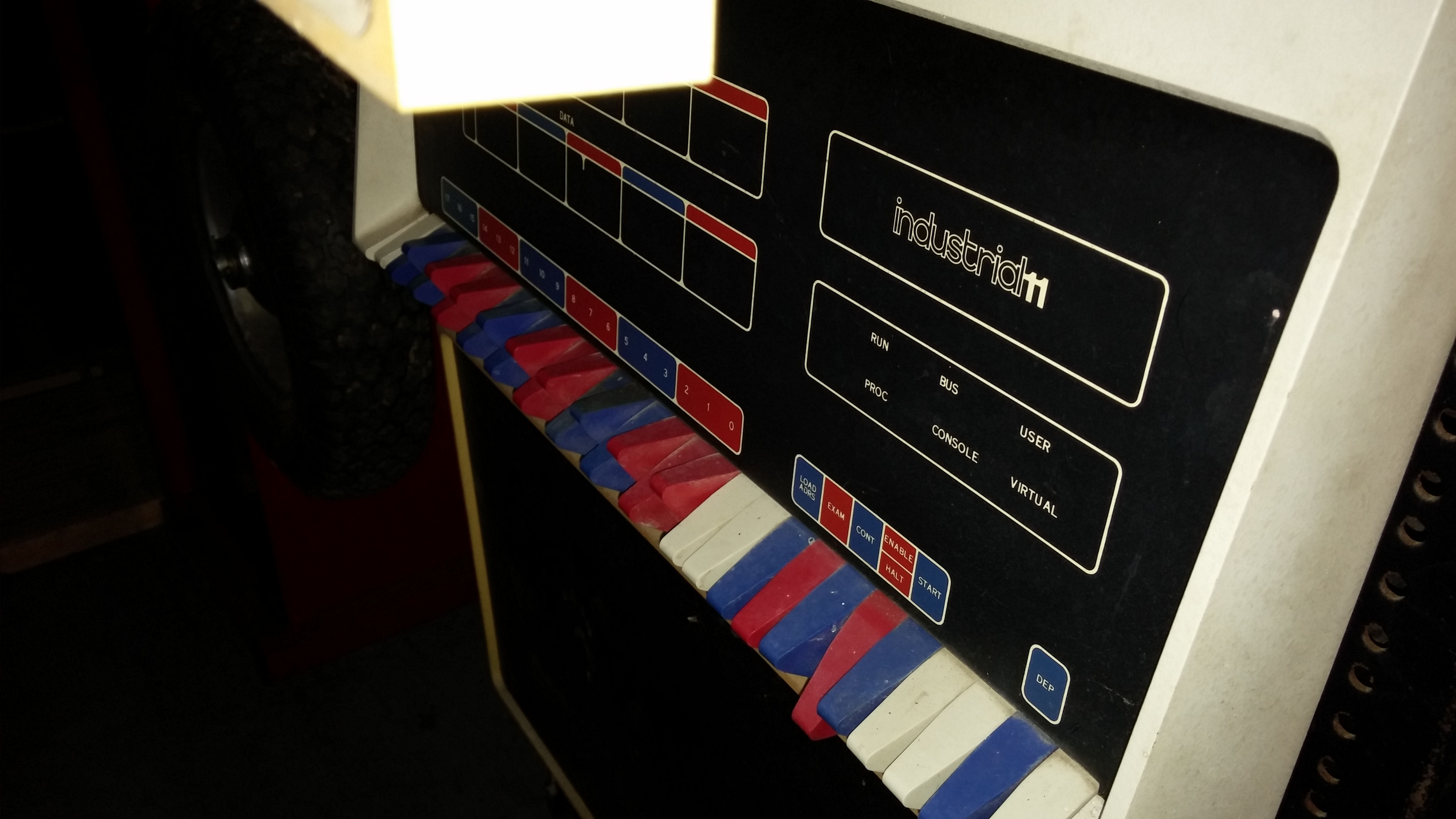
The DEC troubleshooting documentation has some nice decision trees that often end in "swap xyz board" as the solution. In pursuit of my "address light 16 comes on when you press LOAD ADDR" problem, I did just that, swapped CPU boards. One at a time I swapped each CPU board with another (from the Industrial 11). To my surprise there was no change! Each board worked as the board it replaced, I was able to perform front panel tasks as before. What that means, I think:
1) The industrial 11 boards are basically OK, I have a spare set of CPU boards. The only difference is that that the instrial/11 backplane is wired for the M787 option board. 2) The address light did not go out. The problem must be with the front panel itself! If I am right, for now I can just ignore the front panel issue. The light goes out if one hits START and I can go about my business. I will now see about the +15V to the RL11 controller. UPDATE - YUP. I installed the front panel from the 11/40 industrial 11 model here. There were two bad lights, but the address 16 problem was not present. All else being the same, the fault is thus in the front panel. Next: Measure the voltage difference on address line 16 on both front panels, determine failed part by finding the difference and attempt to replace. I can start with logic probe but I assume I will have to use an oscilloscope to locate the fault. Also, while running the industrial/11 panel I can determine which bulbs there are bad. I have spares I can put from this PDP-11 front panel that I can use to replace bulbs. Reply |
|
|
Checking 15V to RL11 |
by Bill Degnan - 12/24/2016 09:37 |
|
Checked the inbound 15V for the DD11-C. I have the distribution panel connector for PDP 11/40's with serial numbers 6000 and higher. The 15V line is a grey wire in hole 2 of the 15-pin (larger) connector on the panel. The exact reading is 15.5, which is within the range the manual requires.
So...is 15V getting to the controller through the backplane wirewrap, or was this wire removed or altered? Where is this measured? Checking manuals to locate the correct pin, so far not found. FROM THE END OF THE RL02 MANUAL: The early SPCs did not utilize Direct Memory Access (DMA) data transfers to/from memory and therefore those signals were not part of the original SPC pin assignments. Some of the newer options, such as the RLII, do utilize DMA transfers. There is a new pin assignment called SPC PRIME that includes these signals. If the RLII is to be used in an older (non SPC-PRIME) slot, then it is necessary to ensure that the following signals are wired on the backplane. • Pin CAl - NPG In • Pin CBI - NPG Out • Pin FJI - NPR • Pin CVI - AC LO • Pin CUI - +15v If the slot has SPC PRIME pinning, then another precaution must be taken. NPG continuity is maintained across an empty SPC PRIME slot by a backplane jumper from pin CAI to pin CB1. This jumper must be removed whenever a DMA-type option is installed, such as an RLll, and the jumper must be added if the module is removed. This consideration is in addition to the normal Bus Grant Continuity card used in row D of all empty SPC slots I put in a riser card and installed a NPGrant card. I measured for 15V and found the pin where 15V was being fed into the controller. I installed the M7762 on a riser card and located the spot where the 15V feeds the first resistor/regulator on the board. Dead. Nothing coming in. Removed the card. Still dead. Somehow this shorted out the h745 killing both 15v and -15V. Now to find a fuse... Bill Reply |
|
|
Testing Required Voltages |
by Bill Degnan - 01/26/2017 09:41 |
|
See thread for h742a repairs.
I think what happened is the riser and the MOS RAM card clinked and shorted the h742a's fuse. So, to continue safely I re-installed the 16K core RAM in a different backplane and removed the MOS ram card so there would be nothing in the DD11-CF backplane except the M9312 ROM and the M7762 RL11 controller (on a full height riser). I found the 15V signal, it is coming into the controller. Next I need to check every single pin in the backplane to see if there is a missing or incorrect voltage being fed into the RL11 controller. I did some of this before, but this time I have to be more thorough. The RL11 will be on a riser so I can probe voltages, hopefully I will not short anything out this time. Reply |
|
|
Success With DD11-B |
by Bill Degnan - 01/30/2017 22:26 |
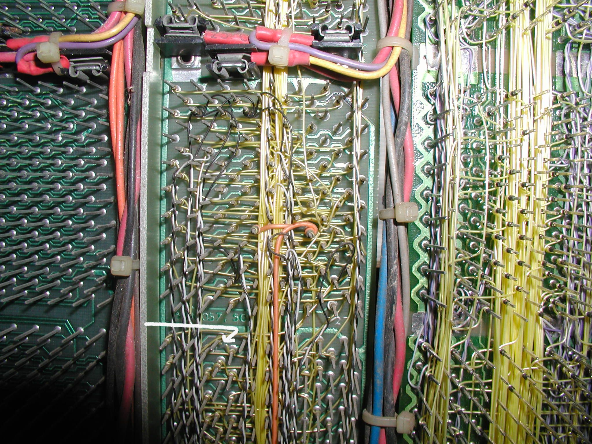 Image of the DD11-B backplane where the CA1 and CB1 jumper was cut. The arrow is pointing to the exact location. Click on the image to zoom out to see the DD11-B (left) and the DD11-CF (right) backplanes.
 The RL11 controller (M7762) was moved from the improperly-functioning DD11-CF backplane (left-most) to the adjacent DD11-B backplane into the slot with the removed NPG jumper. Click image for larger view.
I narrowed the cause of the failure to activate the RL11 controller to the DD11-CF backplane. Not so much technically but logically. To prove my theory, despite my lack of experience I decided that I would remove the NPG jumper from a slot on the adjacent DD11-B backplane and use that slot for the RL11 controller. Assuming power was correct. This worked. End result I can now boot up RT-11 through the RL11 controller and RL02 disk drive. Just remember to remove that one jumper and make sure you have the proper 15V. This set of threads is confusing I know, but here is where we are now 1. Both the PDP 11/40 CPU and industrial/11 CPU are functional. I can swap boards, they're jumpered the same. 2. I transplanted the DD11-B and core memory backplanes from the industrial/11 into the 11/40 chassis because it's cleaner and essentially the same thing. 3. I transplanted the industrial/11 frontpanel to the 11/40 chassis. See thread below. 4. The PDP 11/40 and industrial/11 h742a power supplies both work, but I do not have two complete sets of regulators, unless I borrow one from my 11/05 or fix broken spares on hand. My objective all along has been to use the 11/40 as a test system for restoring the industrial/11. In the process I ended up transplanting most of the industrial/11 system parts into the cleaner 11/40 "short" chassis. Next I will transplant everything back into the full-height DEC cabinet, with the twin RL02 drives. I am going to close this thread. To read more, select from the following choices: industrial/11 restoration thread Booting the System Using RL02 drive Reply |
|
|
XXDP+ |
by Bill Degnan - 02/01/2017 09:36 |
|
Now that I don't need it, because I got everything running correctly and can boot RT-11 for RL02 disk, of course the first random RL02 disk I tested was XXDP+. This kids is how the world works.
Anyway, I loaded the XXDP+ program from RL02 drive 1. The program is not Y2K compatible, so I entered a date of 01-FEB-88 The XXDP+ monitor came up and gave me a dot prompt. Note that when you run a diagnostic, enter ?? at the end so it finds the version that happens to be on your disk, otherwise you'll get a lot of not found errors. For example . R BKTG?? (run KT11-D Exerciser) yawn. Reply |
|
Resources:

Popular Topics and FAQs
Past Issues:
Before we switched over to a blog format, past page archives here:
Vintage Computer Festival East 3.0 June 2006
Commodore B Series Prototypes July 2006
VOLSCAN - The first desktop computer with a GUI? Oct 2006
ROBOTS! - Will Robots Take Over? Nov 2006
Magnavox Mystery - a Computer, or? Jan 2007
The 1973 Williams Paddle Ball Arcade Computer Game Feb 2007
The Sperry UNIVAC 1219 Military Computer May 2007
VCF East 2007 - PET 30th Anniversary June/July 2007
The Electronic Brain August 2007
Community Memory and The People's Computer Company October 2007
Charles Babbage's Calculating Machine December 2007
Vintage Computing - A 1983 Perspective February 2008
Laptops and Portables May 2008
From Giant Brains to Hobby Computers - 1957 to 1977 August 2008
Historic Computer Magazines November 2008
World's Smallest Electronic Brain - Simon (1950) December 2008 - Feb 2009
Free Program Listings Spring 2009
Computer Music Summer 2009
Popular Electronics Jan/Feb 1975 - Altair 8800 Fall 2009
Early Microcomputer Mass Storage Summer 2010
Electronics 19670417
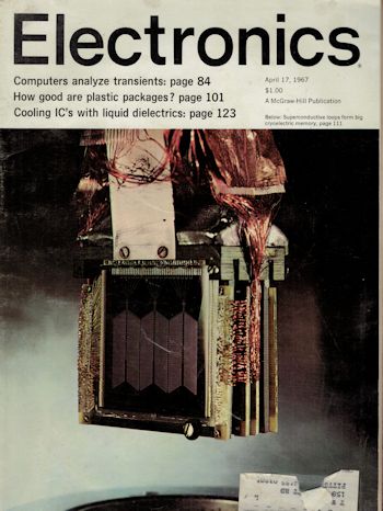
This image was selected at random from the archive. Click image for more photos and files from this set.