Configuring a DL-11 M7800 serial card
SHARE |
|
  Configuring a DL-11 M7800 serial card
 |
by Bill Degnan - 06/14/2016 12:50 |
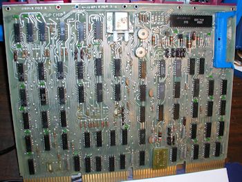
 This DL-11 M7800 serial card was installed in the rear of the PDP 11/40 "industrial11" backplane and was attached to an unknown device by a 1700004-1 flat cable (a.k.a cable with Berg connectors both ends). Click image for larger view.
More photos I don't know what this card was originally connected to, something that communicated at 4800b with 8 data bits. I decided to re-purpose this card and attempt to convert for use with a console terminal at 9600 b 8N1. If I come upon the original device (phone?) I can refer back to the original settings. ------------------------------------------------------ ORIGINAL CONFIGURATION JUMPERS ------------------------------------------------------ Real Time option 540677 5008775B c29 open/out (not 110 baud) c31 open/out (not 100 baud) NP-U out (=no parity/disabled) 2SB-U out (2 SB) EPS out (EPS=even parity when NP is jumrd) NB1/NB2 these two are set together both open = 8 databits. receive crystal 2 o'clock / pos 6 xmit crystal 2 o'clock / pos 6 4608 khz 4800 baud vector address jumper V V7 V6 V5 V4 V3 N 0 1 1 0 0 1 1 address jumpers A3 A4 A5 A6 A7 A8 A9 0 1 1 1 0 0 0 J1 J2 J3 1 0 1 ------------------------------------------------------ CHANGES CONFIGURATION JUMPERS ------------------------------------------------------ These settings work for a 9600b console serial port. Real Time option 540677 5008775B c29 open/out (not 110 baud) c31 open/out (not 100 baud) NP-U out (=no parity/disabled) 2SB-U out (2 Stop Bits) 2SB-U out (2 SB) EPS out (EPS=even parity when NP is jumrd) NB1/NB2 these two are set together both open = 8 databits. receive crystal 4 o'clock / pos 8 xmit crystal 4 o'clock / pos 8 4608 khz 9600 baud vector address jumper V V7 V6 V5 V4 V3 N 0 0 0 1 1 0 1 address jumpers A3 A4 A5 A6 A7 A8 A9 1 0 0 0 1 0 0 J1 J2 J3 1 0 1 This has been confirmed correct, see below. This particular card did not work, but I had another with these settings that does work, and is now installed for use. Reply |
|
  Notes on Jumpers
 |
by Bill Degnan - 06/15/2016 17:48 |
|
From CCTECH Henk Gooijen:
"..The gotcha: for address jumpers a jumper installed makes it a "0", whereas a jumper installed for the vector makes it a "1". I found it pretty confusing, seeing how many scribbled remarks I made on paper :-/ Console address is 777560. The last "0" is A0-A1-A2, and these do not have jumpers. So A5-A4-A3 sets the "6", A8-A7-A6 sets the "5", and A10-A9 sets the low two bits of the "7". (there is no A11). Console vector is 060. Same story. V2-V1-V0 is not available, so you only have to set the "6" (V5-V4 jumpered). To get 9600 Bd, check the crystal. It has to be the frequency listed in the 4th column in the documentation, else 9600 is not selectable. Note that there are two tiny rotary switches on the board. One to set the transmit baudrate, the other the receive baudrate. Testing is easy too. Just LOAD ADDR 777564, then EXAM. If all is correct you will see 0200 (transmit buffer emtpy flag set). Press EXAM again. The "address" is now set to 777566 (transmit buffer). Toggle 073, then DEP. If all is right, you will get a "3" in the terminal. .. ---------- The M7800 described above may be bad, assuming it's now jumpered correctly. ---------- Reply |
|
  Page to Explain Jumpers
 |
by Bill Degnan - 06/16/2016 09:58 |
|
As part of my conversation on CCTECH about the DL11 M7800 cards, I asked Noel Chiappa to chart the jumpers by address. He made a page that explains how the addressing and vectors work and also a chart with how to jumper the first two serial cards in the same system. He produced the following:
"..Anyway, try this on for size: http://gunkies.org/wiki/...synchronous_serial_line If there's anything else I could usefully add there, please let me know. I have provided jumper configs for the console, and the first serial line after that - are there any more that would be useful to list? .." Reply |
|
  Repair Tips
 |
by Bill Degnan - 06/16/2016 12:51 |
|
Tony Duell says in CCTECH:
"..What I would do is : Check that there are transmit and receive clocks at the UART pins (pin 40 and pin 17 IIRC). If missing, check the clock circuitry, crystal, etc. Check that there is a character strobe (I think the UART pin is called 'TRL' -- Transmit Register Load) at the UART when you try to write to the appropriate address. Make sure you don't get a bus timeout error when you do that too. If that's not right, check the address decoder, bus slave logic, etc Check if there is any data coming out the UART on the Transmit register output pin. If not (and if everything else is OK), suspect the UART chip. But check it's not being held reset, it's getting power, etc. .. * * * * One more source site: http://iamvirtual.ca/col...nis/PDP11-10/M7800.html Reply |
|
Resources:

Popular Topics and FAQs
Past Issues:
Before we switched over to a blog format, past page archives here:
Vintage Computer Festival East 3.0 June 2006
Commodore B Series Prototypes July 2006
VOLSCAN - The first desktop computer with a GUI? Oct 2006
ROBOTS! - Will Robots Take Over? Nov 2006
Magnavox Mystery - a Computer, or? Jan 2007
The 1973 Williams Paddle Ball Arcade Computer Game Feb 2007
The Sperry UNIVAC 1219 Military Computer May 2007
VCF East 2007 - PET 30th Anniversary June/July 2007
The Electronic Brain August 2007
Community Memory and The People's Computer Company October 2007
Charles Babbage's Calculating Machine December 2007
Vintage Computing - A 1983 Perspective February 2008
Laptops and Portables May 2008
From Giant Brains to Hobby Computers - 1957 to 1977 August 2008
Historic Computer Magazines November 2008
World's Smallest Electronic Brain - Simon (1950) December 2008 - Feb 2009
Free Program Listings Spring 2009
Computer Music Summer 2009
Popular Electronics Jan/Feb 1975 - Altair 8800 Fall 2009
Early Microcomputer Mass Storage Summer 2010
vcfmw ECCC 2018 Packed With Stuff

This image was selected at random from the archive. Click image for more photos and files from this set.