PTCO 2KRO 1702A 2K ePROM
SHARE |
|
  PTCO 2KRO 1702A 2K ePROM
 |
by Bill Degnan - 04/17/2013 15:25 |
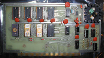
 Processor Technologies PTCO 2KRO 1702A 2K eProm Board, .cir 1976. Click for larger View.
Here is a dump extracted from three 1702-A ePROMs installed in a PTCO 2KRO board. The dump below consists of the three 1702-A ROMs. The first is (my guess) some sort of 8080 monitor program or bootstrap, the second is the PTCO VDM-1 board initialization routine, and the third may be additional instructions for a 3P+S card to interface to run with a teletype (ASR33?). Just a guess. I will update the thread after I get a chance to test. I also have to determine the memory locations of each. The card is not documented on the web. The jumper W is in the "1" position. I am guessing 1 = C000, 2 = D000, 3=E000, 4=F000 - I will update this thread after I run some tests. 00: 31 FF 2F CD 06 80 CD 45 80 FE 3A C2 06 80 CD 2A 10: 80 57 C8 CD 2A 80 67 CD 2A 80 6F CD 2A 80 CD 2A 20: 80 77 23 15 C2 1E 80 C3 06 80 CD 45 80 CD 3D 80 30: 07 17 17 17 5F CD 45 80 CD 3D 80 83 C9 D6 30 FE 40: 0A D8 D6 07 C9 DB 00 E6 40 CA 45 80 DB 01 D3 FF 50: E6 7F C9 00 00 00 00 00 00 00 00 00 00 00 00 00 60: 31 FF 2F CD 66 80 CD C2 80 FE 3A C2 66 80 CD 8A 70: 80 57 C8 CD 8A 80 67 CD 8A 80 6F CD 8A 80 CD 8A 80: 80 77 23 15 C2 7E 80 C3 66 80 CD C2 80 CD 9D 80 90: 07 17 17 17 5F CD C2 80 CD 9D 80 83 C9 D6 30 FE A0: 0A D8 D6 07 C9 DB 02 DB 02 31 FF 2F 21 00 00 CD B0: C2 80 B7 CA AF 80 77 BE C2 B8 80 23 CD C2 80 C3 C0: B6 80 DB 00 E6 01 C2 C2 80 DB 00 E6 01 CA C9 80 D0: DB 02 E6 7F C9 00 00 00 DB 00 E6 80 CA D8 80 78 E0: D3 01 FE 0D C0 E5 AF 6F 67 EB EB 2C C2 E9 80 24 F0: C2 E9 80 E1 C9 00 00 00 00 00 00 00 00 00 00 00 00: 22 F9 2F 21 00 00 39 31 F8 2F E5 D5 C5 F5 CD B3 10: 81 F1 C1 D1 E1 F9 2A F9 2F C9 78 E6 7F FE 0C CA 20: 35 81 FE 5F CA 8E 81 FE 0D CA 9D 81 FE 7F C8 FE 30: 20 D8 C3 80 81 3E 00 D3 C8 32 FD 2F 21 00 CC 11 40: 40 00 06 10 36 0D 19 05 C2 44 81 C3 4E 81 21 C0 50: CF 22 FB 2F 36 A0 23 36 0D C9 3A FD 2F 3C E6 0F 60: 32 FD 2F D3 C8 2A FB 2F 11 40 00 7D E6 C0 6F 19 70: 7C E6 03 F6 CC 67 C3 51 81 2A FB 2F 3E 3F A5 C9 80: CD 79 81 FE 3F C8 3E 7F A0 77 23 C3 51 81 CD 79 90: 81 C8 36 0D 2B 22 FB 2F 3E 80 B6 77 C9 CD 79 81 A0: 36 0D CD A8 81 C3 5A 81 DB FF E6 40 C8 CD C2 80 B0: DB 03 C9 DB FF E6 01 CA 1A 81 C3 D8 80 00 00 00 C0: 31 FF 2F 21 00 00 CD D7 81 B7 CA C6 81 77 D3 FF D0: 23 CD D7 81 C3 CD 81 DB 00 E6 01 C2 D7 81 DB 00 E0: E6 01 CA DE 81 DB 02 C9 00 00 00 00 00 00 00 00 F0: 00 00 00 00 00 00 00 00 00 00 00 00 00 00 00 00 00: CD 35 81 CD 45 80 DB 01 C3 60 82 CD 00 81 DB FF 10: FE 10 CC 35 81 DB FF FE 08 CA 04 C0 C3 03 82 00 20: 45 0A 41 20 53 49 55 0D 44 52 4A 4E 46 43 4B 54 30: 5A 4C 57 48 59 50 51 4F 42 47 00 4D 58 56 00 00 40: 33 00 2D 20 07 38 37 0D 24 34 27 2C 21 3A 28 35 50: 22 29 32 23 36 30 31 39 3F 26 00 2E 2F 2E 00 00 60: FE 1B CA 7A 82 FE 1F CA 82 82 21 1F 82 5F 16 00 70: 19 3A 00 C9 5F 19 46 C3 0B 82 3E 20 32 00 C9 C3 80: 03 82 AF 32 00 C9 C3 03 82 00 00 00 00 00 00 00 90: 00 00 00 00 00 00 00 00 00 00 00 00 00 00 00 00 A0: 00 00 00 00 00 00 00 00 00 00 00 00 00 00 00 00 B0: 00 00 00 00 00 00 00 00 00 00 00 00 00 00 00 00 C0: 00 00 00 00 00 00 00 00 00 00 00 00 00 00 00 00 D0: 00 00 00 00 00 00 00 00 00 00 00 00 00 00 00 00 E0: 00 00 00 00 00 00 00 00 00 00 00 00 00 00 00 00 F0: 00 00 00 00 00 00 00 00 00 00 00 00 00 00 00 00 Reply |
|
  Update to PTCO 2KRO
 |
by Bill Degnan - 12/19/2015 15:18 |
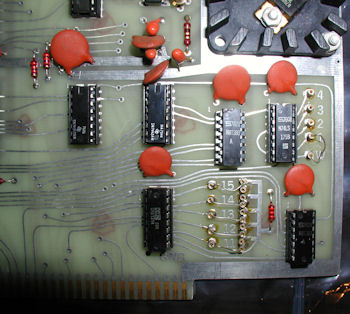
 View of the 2KRO jumpers. Click for larger View.
I installed this S-100 board into my IMSAI 8080 to see if I can read the ePROMs from the front panel having already verified the chips are OK (see also 1702A repair below). I have no manual for this board (have one?). A little experimentation revealed how to assign the page address using jumpers 11-15. In the photo above, note how jumper 15 is set to the top jumper (or "high") post and the rest are connected to the "low" posts. This combination sets the starting page address of the board to 80H (8000 0000 Hex). When I change jumper set 15 to the low post, starting page address becomes 0000 0000 Hex. The wait state jumper posts read W and 1-4. The photo shows how the jumper is set to connect to jumper 1, indicating no wait state needed (I believe). Reply |
|
  Repairing Legs of a 1702A ePROM
 |
by Bill Degnan - 12/22/2015 15:25 |
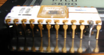
 This photo shows a 256 byte 1702A ePROM with a broken pin, since repaired (note silver-colored pin 2nd from right). The ePROM repair was a success, but given its fragile state I replaced from use and installed a newer 1702A onto the ePROM board, see photo above. Fortunately I had an image of the ePROM and was able to make a replacement chip. Click for larger View.
Reply |
|
Resources:

Popular Topics and FAQs
Past Issues:
Before we switched over to a blog format, past page archives here:
Vintage Computer Festival East 3.0 June 2006
Commodore B Series Prototypes July 2006
VOLSCAN - The first desktop computer with a GUI? Oct 2006
ROBOTS! - Will Robots Take Over? Nov 2006
Magnavox Mystery - a Computer, or? Jan 2007
The 1973 Williams Paddle Ball Arcade Computer Game Feb 2007
The Sperry UNIVAC 1219 Military Computer May 2007
VCF East 2007 - PET 30th Anniversary June/July 2007
The Electronic Brain August 2007
Community Memory and The People's Computer Company October 2007
Charles Babbage's Calculating Machine December 2007
Vintage Computing - A 1983 Perspective February 2008
Laptops and Portables May 2008
From Giant Brains to Hobby Computers - 1957 to 1977 August 2008
Historic Computer Magazines November 2008
World's Smallest Electronic Brain - Simon (1950) December 2008 - Feb 2009
Free Program Listings Spring 2009
Computer Music Summer 2009
Popular Electronics Jan/Feb 1975 - Altair 8800 Fall 2009
Early Microcomputer Mass Storage Summer 2010
telecomputing system

This image was selected at random from the archive. Click image for more photos and files from this set.