Teletype ASR 33 S/N 256219 Repair
SHARE |
|
 Teletype ASR 33 S/N 256219 Repair
 |
by Bill Degnan - 06/04/2012 23:37 |
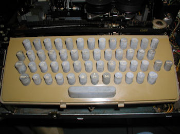 The keyboard of the Teletype Model ASR 33. The cover of the teletype has been removed.
I have been working to restore teletypes lately. I am almost done with this one, in fact it was running just fine until I read in a long tape using the reader. Afterwards I noticed that the characters that use the 6th channel/cam to print characters from the keyboard was being switched with channel/cam 7. For example, if you hit the "4" key, the printer prints a T instead. The Model 33 typewheel code chart says that the 4 is printed using channel 3-5-6-8. A "T" is printed by using channels 3-5-7-8. I have asked Wayne from the GreenKeys mailing list for help. He has a teletype repair and restoration business and I highly recommend his services. Closeup pictures of Teletype ASR 33 S/N 256219 Reply |
|
 Fixing incorrect character problems
 |
by Bill Degnan - 06/05/2012 20:34 |
|
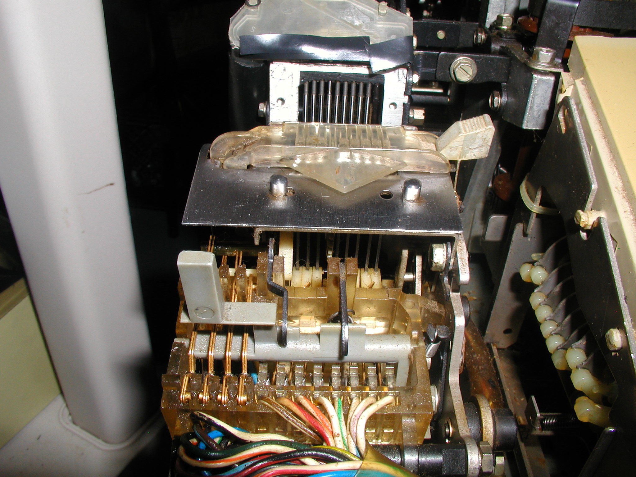
Here is a picture of the source of the bad character problem. Look at this picture in it's full size. There are 4 gold-colored double pins coming from the left front of reader and 8 wires to the right. Each of these 8 wires also connect to long golden-colored pins. The end of these pins is supposed to fit into little notches. The 2nd to the right of those 8 was out of it's notch. I carefully pulled on the spring holding the pin and let it fall back naturally into the correct slot.
Fixed! Reply |
|
|
ASR 33 Will Not Enter Local Mode |
by Bill Degnan - 09/11/2012 21:52 |
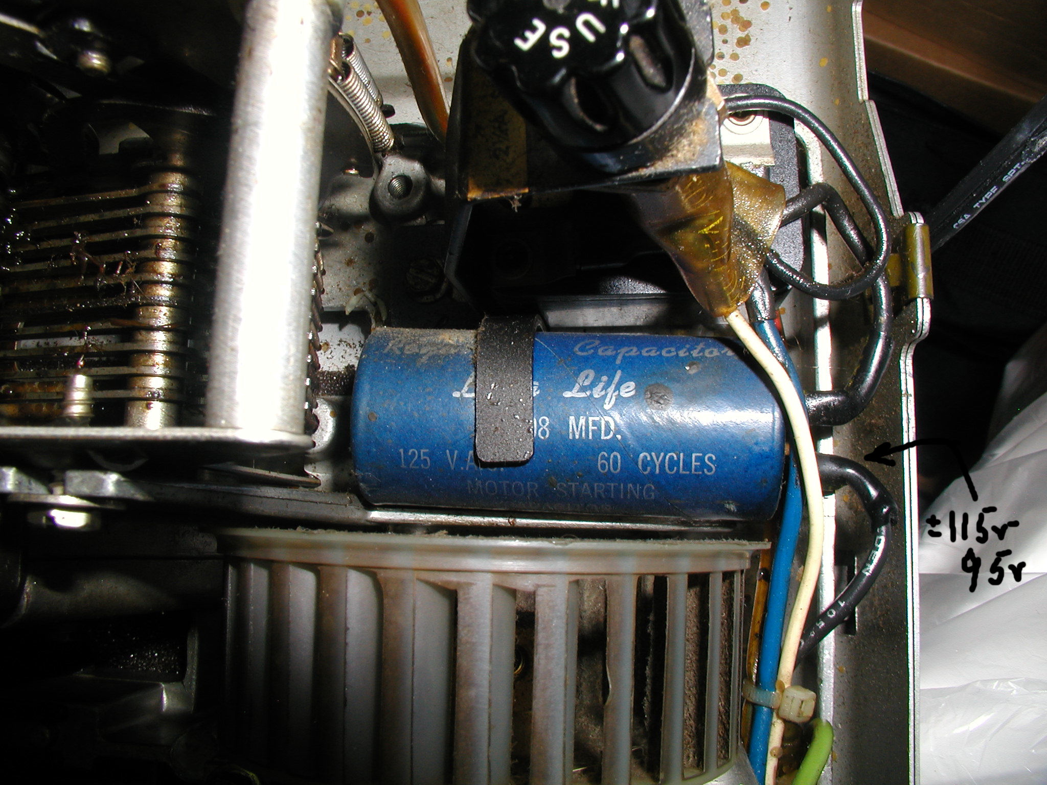 From the back of the teletype on the right is a lone fuse. Attached to the fuse is a capacitor, which leads to a relay and eventually the motor. The cap is supposed to be 108 mfd 125v. When the the current loop is in place, I believe this cap and fuse are involved in causing the chattering to stop and causing the teletype to take input from the local keyboard or an external computer. Click image for larger view.
 You can test the voltage by measuring the upper left and lower right connection points. The value should range between 95-120 depending on the function of the machine at the time. Click image for larger view.
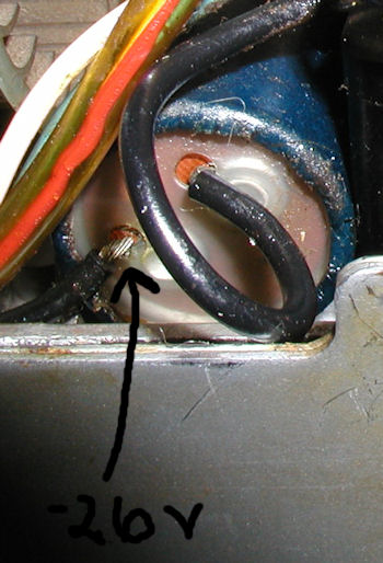 I have one working teletype to compare with. I tested the fuse to be OK. I found however that the reading from the cap near the fuse is far too low, measuring only +- 26V (not sure if it should be plus or minus). I compared with the same points in a working TTY, which were in the 95v-115v range. Click image for larger view.
I *assume* that because the voltage coming from the cap is so low, the motor will not receive enough voltage to stop it from chattering, the current loop is not completed. Stay tuned this is just a guess, let's see ... Reply |
|
|
Restoration Complete |
by Bill Degnan - 11/29/2012 22:33 |
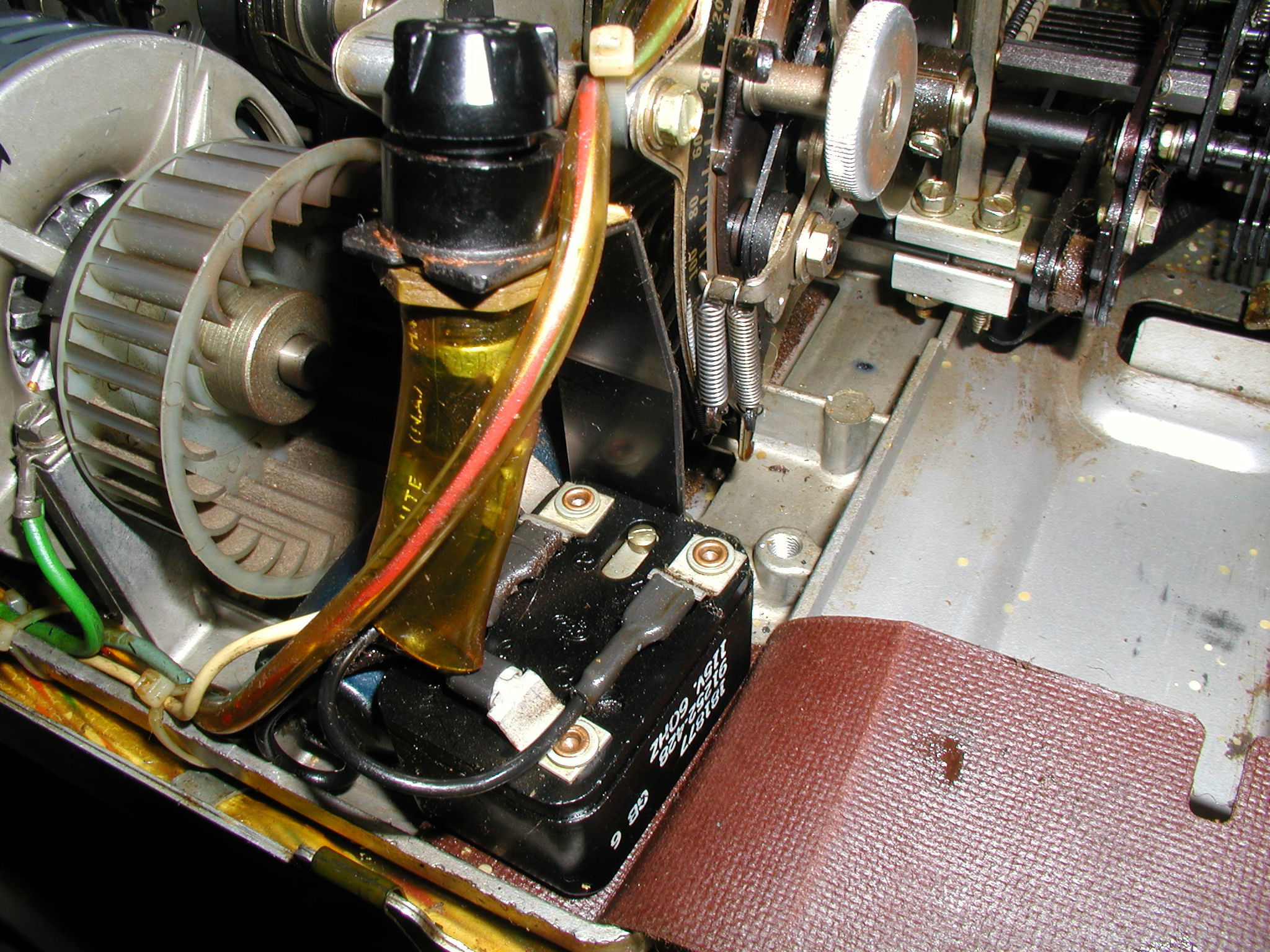
 Teletype model ASR 33 restoration complete. Pictured here is a view with some of the outer cover components removed. Click images for larger view.
I was wrong about the capacitor, I tried it in another teletype and it worked just fine. In fact I tested three caps so now I have a spare for the future. I also tested the motor relay (which works), re-soldered the UCC-6 controller card resistor joints, and replaced the UCC-6 itself. I found nothing wrong and I was still at a loss to determine why the teletype was running open in LINE and LOCAL modes. Then I found the source of the problem. The BREAK key pin was out of its joint under the keyboard, just slightly, but enough to be constantly "on". I must have caused this issue when I vacuumed the insides of the TTY after running a long punch job without a chad catch cover on the punch pins. Note - don't ever try this.. What a mess! By re-aligning the pin into its slot, the TTY now closes in LOCAL mode or when engaged by a computer system sending a current loop.  A new unit cover and punch chad catch cover installed. Click image for larger view.
Finishing touches: 1. I replaced the cover, paper advance knob, and re-aligned the papertape reader. 2. I tested the system using my SWTPC and PDP 11/05. For the first time I got a good print from the 11/05. (I will come back to that later). 3. Wayne D. sent me a papertape punch chad cover (triangular plastic thing) which I installed. 4. I read a long papertape (TSC BASIC) using the reader, successfully loaded BASIC, customized it, and punched the customized copy to tape. 5. I fashioned a new cable for the computer. Done. Took a few new pictures. Reply |
|
Resources:

Popular Topics and FAQs
Past Issues:
Before we switched over to a blog format, past page archives here:
Vintage Computer Festival East 3.0 June 2006
Commodore B Series Prototypes July 2006
VOLSCAN - The first desktop computer with a GUI? Oct 2006
ROBOTS! - Will Robots Take Over? Nov 2006
Magnavox Mystery - a Computer, or? Jan 2007
The 1973 Williams Paddle Ball Arcade Computer Game Feb 2007
The Sperry UNIVAC 1219 Military Computer May 2007
VCF East 2007 - PET 30th Anniversary June/July 2007
The Electronic Brain August 2007
Community Memory and The People's Computer Company October 2007
Charles Babbage's Calculating Machine December 2007
Vintage Computing - A 1983 Perspective February 2008
Laptops and Portables May 2008
From Giant Brains to Hobby Computers - 1957 to 1977 August 2008
Historic Computer Magazines November 2008
World's Smallest Electronic Brain - Simon (1950) December 2008 - Feb 2009
Free Program Listings Spring 2009
Computer Music Summer 2009
Popular Electronics Jan/Feb 1975 - Altair 8800 Fall 2009
Early Microcomputer Mass Storage Summer 2010
3000 2
This image was selected at random from the archive. Click image for more photos and files from this set.