Processor Tech SOL 20 Terminal Computer
SHARE |
|
 Processor Tech SOL 20 Terminal Computer
 |
by Bill Degnan - 07/01/2009 08:21 |
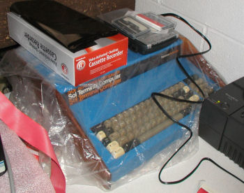 The Processor Technologies SOL-20 Computer
As with most projects, the first thing that needs to be done is check the 5V output to the motherboard. I assisted Dan Roganti test the power supply and we compared with another power supply to confirm the results. The SOL supply is OK, or at least it compares with a known-working supply. The voltage reading on the board however is not OK. 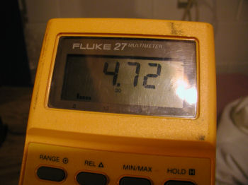 The DC Voltage is consistently below 5V, something is shorting out.
The next step is to remove all socketed chips to see if there are bad TTL chip causing the voltage problem. 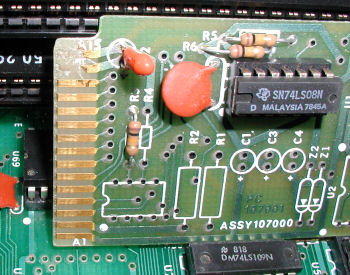 The SOLOS Personality ROM daughterboard. Note how two connectors are cut...need to find out if this is intentional or damage. The SOLOS Personality ROM daughterboard. Note how two connectors are cut...need to find out if this is intentional or damage.
More Pics Reply |
|
 SOL-20 8080 in circuit emulator testing
 |
by Bill Degnan - 08/01/2011 23:27 |
|
Using The 8080 in-circuit emulator by Tauntek
http://tauntek.com/8080-In-Circuit-Emulator.htm I ran a few tests. With the SOLOS card installed the ICE detected something in in memory after C000-C800, presumably the SOLOS ROM. I put in a known-working RAM card to populate 0000-1FFF. Something is in RAM, but I can't do much with it. Testing with the Altair 8800a was much more productive, I will report more findings in a separate thread. Reply |
|
|
SOL-20 Update from MARCH Workshop |
by Bill Degnan - 07/05/2012 02:03 |
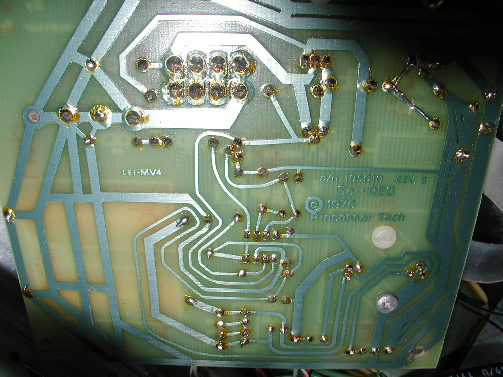
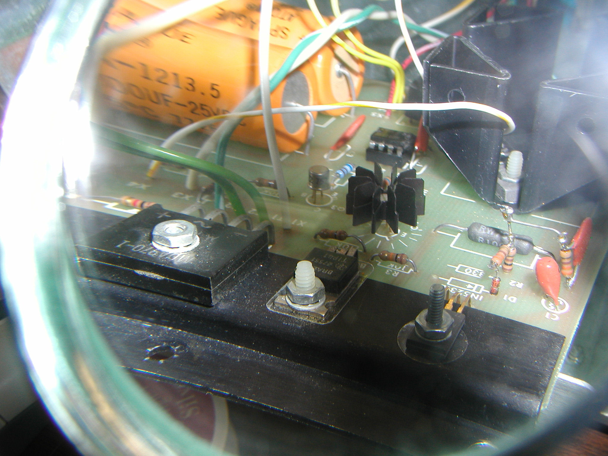 A photo of the rear power supply components taken through a magnifying glass. Click image for larger view. Here's a pic of the bottom of the board. Note the repaired trace in the corner.
Re-seating the chips and/or using the system for a few hours boosted the overall motherboard power reading closer to +5V (4.86). These readings are almost exactly the same as a working SOL-20 I used to compare with. I decided it was time to probe into the logic components next. 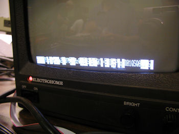 A photo of the display after halting the processor by using the in-circuit emulator. I don't have a picture of the display while the system is running, but the system sends a constant stream of the ASCII character FF to the screen.
Herb Johnson set up his oscilloscope so I could probe the circuits, plus none other than Lee Felsenstein was there for a few hours to observe our progress towards restoring Herb and my SOL-20. Not bad company. Bill S also brought his SOL and made a few OS disks for us. Fortunately the SOL-20 Herb Johnson brought along worked (he had never tried it before, what luck!) I was able to use his working system to compare and contrast with mine. We found little differences in performance after a number of hours of testing. The problem with my system is not obvious and more work is required. Where things stand at the moment is that the system cannot write to RAM. It gets as far as reading (or attempting to read) the SOLOS ROM, but whatever the next step is after that fails. We spent many hours working through the checkout procedure from the SOL-20 manual. We were not able to find the cause of the problem yet, I will post our findings and update this post asap. If you look at my earlier post the in-circuit emulator showed that I did see something in C000 two years ago, I need to re-test that. Maybe I simply have some bad RAM. If the first video RAM chip were bad that could possibly explain why the system cannot get past this point. It could also be a TTL chip issue I have not id'd yet. Herb started working on his keyboard pads. I have not yet started restoring the keyboard, but I am able to use the keyboard without the cover and keys, by pressing my fingers on the bare board connectors. In the earlier post, I mentioned how the two edge connector lines on the personality board were cut...this is done because at some point PT changed the type of ROM they use in their personality modules. The newer version does not need the signals so they cut the traces. To be sure, my personality module was tested in Herb's working system. So we know that's OK. NEXT: Test RAM, post more details from the workshop (I have more notes). Then set up my oscilloscope and run more tests by following the check-out procedures from the manual. Also, there are online resources found on http://www.sol20.org New Photos posted from June 30 2012 workshop About Lee Felsenstein: http://en.wikipedia.org/wiki/Lee_Felsenstein Reply |
|
|
Progress |
by Bill Degnan - 02/12/2014 10:43 |
|
tested all chips that my tester could read.
4013 bad in U113 need to replace. 7410 bad in U47 replaced. I re-set jumpers correctly per Sol-20 manual NOW - I see a line of 909090 at the bottom of the screen instead of the garbled characters. Keyboard found to have an un-soldered IC in slot C7, making me wonder if keyboard assembly is OK. Tested IC's in keyboard that were recognized by my TTL chip tester, all OK. I need to test voltages, logic probe, etc. Plugging in the keyboard turns off the display. There must be a short. I will see if I can track it down. The keyboard may not have been finished, given C7 was not soldered to the keyboard board. My IC tester says the chips are OK so what else could be bad/incomplete? Lights inconsistently respond to key presses on bare board. I am certain the keyboard is plugged in correctly. I have another keyboard I can rig that will work on this system. I need to test manually the RAM and the ICs that the TTL chip tester I have cannot. Reply |
|
|
9090909090 |
by Bill Degnan - 02/14/2014 10:43 |
|
update - 90909090 means the monitor is crashing (I believe)...meaning possibly RAM is bad OR TTL chip or CAP or.... whatever in circuit that supports these two.
All but 2102 U5 and U16 Probe pin 11 - steady LO, steady HI, pulse visible 2102 U5 and U16 Probe pin 11 - no/weak LO, steady HI, pulse visible. swapped RAM, same issue. means problem is with the board. Reply |
|
Resources:

Popular Topics and FAQs
Past Issues:
Before we switched over to a blog format, past page archives here:
Vintage Computer Festival East 3.0 June 2006
Commodore B Series Prototypes July 2006
VOLSCAN - The first desktop computer with a GUI? Oct 2006
ROBOTS! - Will Robots Take Over? Nov 2006
Magnavox Mystery - a Computer, or? Jan 2007
The 1973 Williams Paddle Ball Arcade Computer Game Feb 2007
The Sperry UNIVAC 1219 Military Computer May 2007
VCF East 2007 - PET 30th Anniversary June/July 2007
The Electronic Brain August 2007
Community Memory and The People's Computer Company October 2007
Charles Babbage's Calculating Machine December 2007
Vintage Computing - A 1983 Perspective February 2008
Laptops and Portables May 2008
From Giant Brains to Hobby Computers - 1957 to 1977 August 2008
Historic Computer Magazines November 2008
World's Smallest Electronic Brain - Simon (1950) December 2008 - Feb 2009
Free Program Listings Spring 2009
Computer Music Summer 2009
Popular Electronics Jan/Feb 1975 - Altair 8800 Fall 2009
Early Microcomputer Mass Storage Summer 2010
vintage computer books
This image was selected at random from the archive. Click image for more photos and files from this set.