EPSON PX-8 Operating System Reference Manual, Y20499006100, chapter 3
Chapter 3 MAPLE CP/M Principles of Operation
MAPLE adopts CP/M Version 2.2 as its operating system. Since the basic part of the MAPLE operating system is implemented in ROM, MAPLE CP/M runs in a slightly different way from the CP/M for most disk—based computers. This chapter explains how MAPLE CP/M run on the MAPLE computing system.
3.1 CP/M Memory Organization
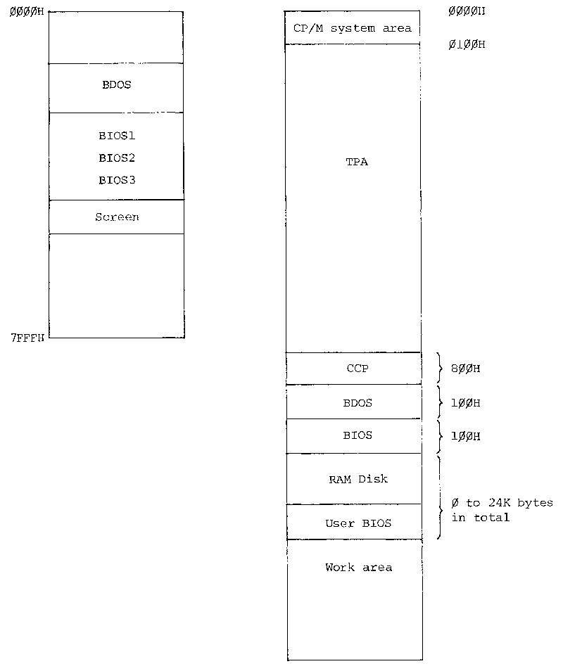
3.1.1 Roles of CP/M Modules in ROM and RAM MAPLE CP/M switches between two 32K—byte banks during execution using a bank switching technique as shown in the figure on the next page. One is a ROM bank containing the major portions of CP/M OS and the other is a RAM bank which makes up the first half of the 64K main RAM memory. The CP/M modules (CCP, BDOS, and BIOS) are apparently loaded in RAM as they are on ordinary disk—based computers. This means that MAPLE application programs can use the CP/M functions in the same way as those which use the standard CP/M. In fact, however, only a 100H bytes of a system area containing the entry points to the BDOS and BIOS are loaded in RAM, making the most part of the RAM
3-1
available for application programs. Actual BDOS and BIOS operations are performed in the OS in ROM that is activated through bank switching. Control is returned to the application program again through bank switching to RAM after processing is terminated.
3-2
3-3
The addresses of the CCP, BDOS, and BIOS in RAM differ depending on the total size of the RAM disk implemented and the user BIOS area (O — 24K bytes). The size of the CP/M system ranges from 59.5K to 45.5K bytes. The RAM disk and user BIOS sizes can be changed by the CONFIG program.
3-4
3.1.2 Procedure for Constructing a CP/M System in RAM
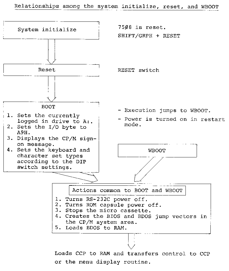
On MAPLE, the CP/M system can be loaded from ROM into RAM by three routines: system initialize, reset (CBOOT), and WBOOT. This subsection describes the function of these routines and the timing when they are invoked as well as the interactions between them. The STOP and CTRL/STOP functions for interrupting program execution are also explained here.
The user can take the following measures (must be attempted in this sequence) when his program hangs up:
1. Press the STOP key.
2. Press STOP key while holding down the CTRL key.
3. Press the RESET switch.
4. Hold the SHIFT and GRPH keys simultaneously and press the RESET switch on the side of MAPLE.
5. Press the 7508 RESET switch.
3-5
| Operation | Initiated by | When | |
|---|---|---|---|
| System initialize |
1. Initializes system area 1. 2. Resets the slave CPU 6301. 3. Checks the extended RAM disk unit. 4. Performs system initialization. Sets the year, month, day, hour, minute, and second and the size of the RAM disk and User BIOS. (ASCII Version 1.0 and Japanese-language OS) 5. In ASCII Version B, the system initialization formats the RAM disk and only initializes the system as follows without performing system initialization: Date and time: 1900/00/00 00:00:00 Sunday RAM DISK: 9K bytes User BIOS: 0 bytes | 1. Pressing the 7508 RESET switch. 2. Holding the SHIFT and GRPH keys down and pressing the RESET switch. | 1. Using the system for the first time after purchase. 2. 7508 hangs up. 3. The extension unit is installed or removed. |
| Reset | 1. Initializes system area 2. 2. Resets the slave CPU 6301. 3. Loads the BIOS to RAM. 4. Checks the RAM disk checksum. 5. Sets the screen to the mode specified by CONFIG. |
1. Pressing the RESET switch. | 1. Z80 hangs up. 2. 6301 hangs up. |
| WBOOT | 1. Flushes the FD buffer. 2. Sets the cursor to the mode set up by CONFIG. |
1. Entering C or the STOP key in CCP mode. 2. Sending control to WBOOT in the program. 3. Turning power on in restart mode. |
1. Control jumps to BIOS WBOOT. |
| CTRL/STOP | 1. Interrupts the current I/O operation. 2. Clears the key buffer and loads it with 03H. |
1. When holding down the CTRL key and pressing the STOP key. | 1. Interrupting application program prforming an I/O operation. The application program must terminate on receiving 03H. |
| STOP | 1. Clears the key buffer and loads it with 03H. | 1. Pressing the STOP key. | 1. When interrupting the application program must terminate on receiving 03H. |
3-6 / 3-7
3-8
System areas 1, 2, and 3
The RAM work area that MAPLE uses is classified into the following two types:
1. Work areas initialized at a specific timing before use.
2. work areas used only temporarily.
The work area of the first type is divided into three types called system areas 1, 2, and 3 according to the timing at which initial values are set.
| Initialized when | Work area contents | |
|---|---|---|
| System area 1 | System initialize is invoked. | Initial values of flags indication PASSWORD and MAPLE basic status. |
| System area 2 | Reset is invoked. | Initial values related to BIOS. |
| System area 3 | WBOOT is invoked. | Initial values related to BDOS. |
3-9
3.2 BDOS Function Processing Flow
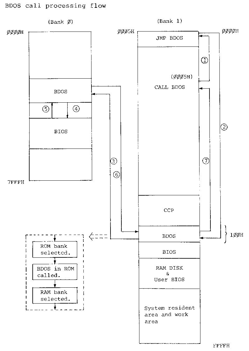
when BDOS is called by a MAPLE application program, control is first transferred to the entry point to the BDOS in RAM. Then the OS switches banks and maps the memory addresses 0000H to 7FFFH into ROM, then calls the real BDOS in ROM. Upon completion of processing, the OS switches the bank to RAM and returns control to the application program with return information loaded in registers.
The BDOS in ROM calls directly the BIOS in ROM.
>3-1O
3.11
3.3 BDOS Error Recovery Procedure
BDOS can display four types of error conditions. Since these errors are handled totally under BDOS control, it is likely that they destroy the current screen image, initiates a warm boot on receipt of user response from the keyboard after the error display, or even destroy memory data. One of countermeasures to avoid this is to make the application program report and handle error conditions for itself. The MAPLE OS permits the application program to take the following two measures against error conditions to achieve this:
1. Receiving BDOS error information as a return code.
2. Rewriting the jump vector for BDOS error processing and performing user-supplied error processing.
The four types of BDOS errors are:
1. Bad Sector
2. Bad Select
3. R/O Disk
4. R/O File
3-12
3.3.1 Receiving BDOS Error Information in Return Code
(1) Changing the BDOS error reporting mode The application program can receive any BDOS error information directly in CPU registers by calling location 0012H (SET ERROR) in OS ROM (bank 0). It can also have BDOS return any error information by calling location 0015H (RESET ERROR) in OS ROM.
The application program must use BIOS CALLX (WBOOT + 69H) to directly call a routine in OS ROM. In this case, the program must reserve a stack area at a it location 8000H or higher in RAM.
3-13
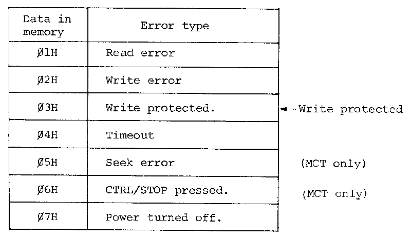
(2) Return codes
For Bad Sector errors, BDOS stores more detailed error information in memory.
BIOSERROR EQU 0F536H
3-14
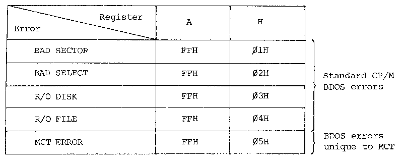
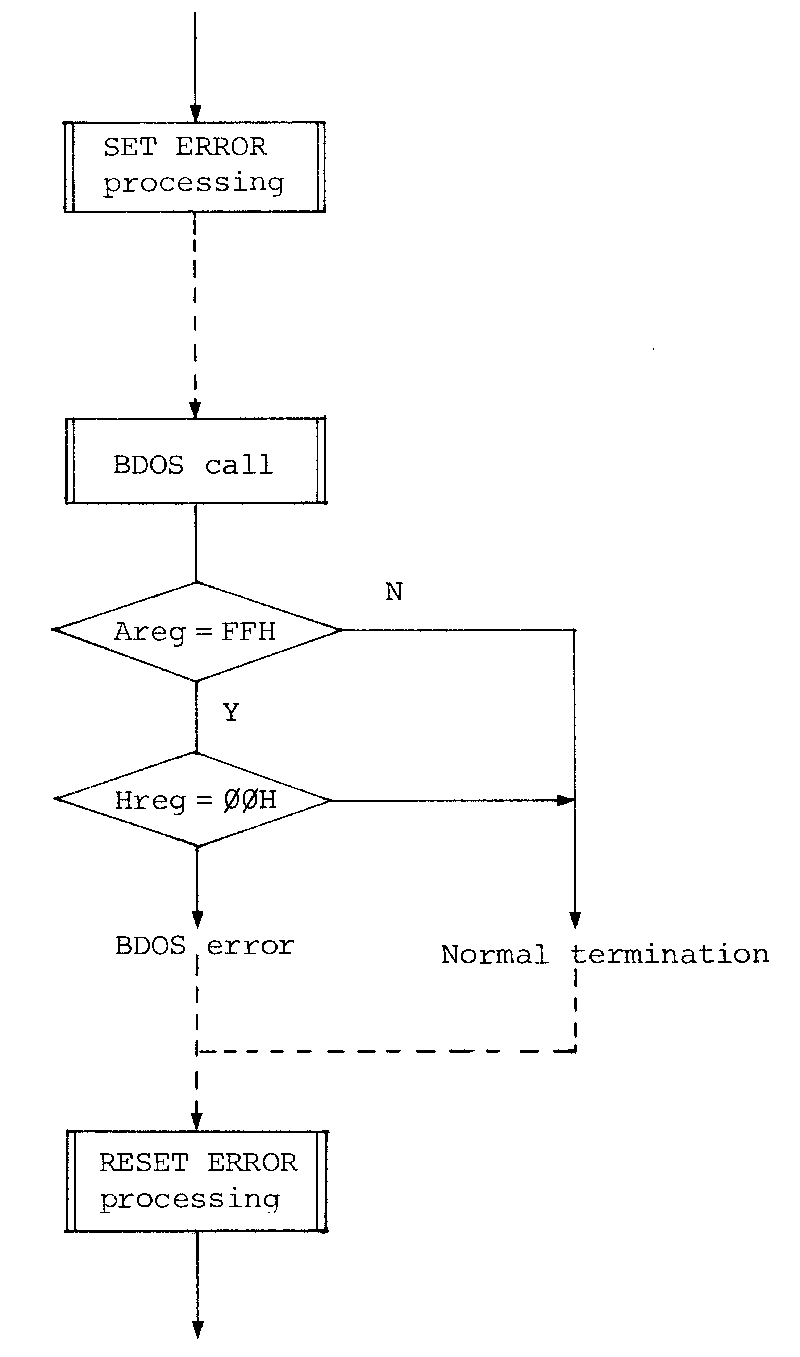
(3) Procedure for identifying errors
Some of the BDOS functions return 0FFH to the A register as a usual return code. Therefore, the calling program must identify errors by examining the H register as well as the A register. See the figure below.
3-15
(4) Programming notes
1) Once SET ERROR is executed, BDOS performs no error processing and continues only to return error status until a RESET ERROR or WBOOT is executed.
2) After execution of SET ERROR, the results are not guaranteed unless the application program performs its own error checking and recovery processing.
3-16
3.3.2 Rewriting the Jump Vector for Processing BDOS Errors
Four jump vectors for processing BDOS errors are located at the beginning of BDOS in RAM. The application program can handles error conditions in its own way by changing the contents of these jump vectors.
ERRVCTR: <-----------------

             Address ((Contents of RAM address 6 and 7)+3)

   DW PERERR <---- Address of parameter error processing routine
                    (Bad Sector error)
   DW SELERR <---- Address of select error processing routine
                    (Bad Select error)
   DW RODERR <---- Address of read only disk error processing
                    routine (R/O Disk error)
   DW ROFERR <---- Address of read only file error processing
                    routine (R/O File error)
        ^
        |
        |
The application program can perform its own error processing by changing the above addresses.
3-17
Programming notes:
(1) On return, the stack area is switched to that for the application program because the stack area for the BDOS was used during BDOS processing.
(2) Bank 1 is selected (all RAM).
(3) The user error processing routine must contain no BDOS calls if it is to return control to BDOS with a RET statement.
3-18
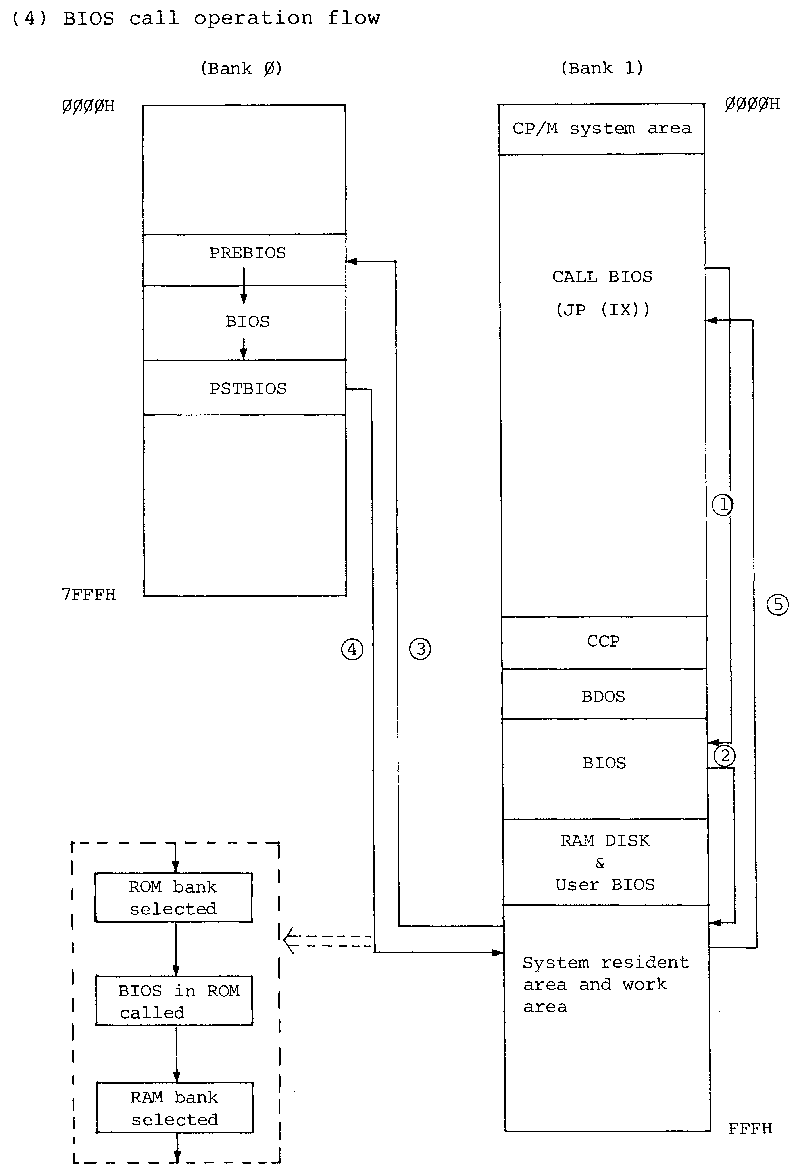
3.4 BIOS Function Operation Flow
(1) Outline
The major BIOS operations are carried out by BIOS in ROM as BDOS operations are. To achieve these, when a call to BIOS is made from an application program, the OS receives the call in the BIOS in RAM, switches the active bank to the system bank, and calls the BIOS in the system bank (ROM). After completion of the BIOS processing, the OS returns to the BIOS in RAM with various return information and result data, switching again to the user bank, and returns control to the application program.
The BIOS in RAM always resides in addresses higher than 8000H so that it is not affected by bank switching.
3-19
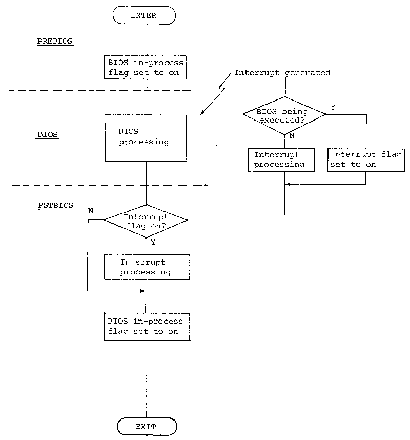
(2) PREBIOS and PSTBIOS
Some BIOS routines uses the slave CPU functions (e.g., screen and microcassette handling). Since the main and slave CPUs communicate commands and data using a specific protocol, if the main CPU attempts to request the slave CPU to do one operation while it has already instructed the slave CPU to do another operation, the protocol will be destroyed and the communication between the main and slave CPUs hang up. BIOS controls the slave CPU properly while BIOS alone is using the slave CPU. If, however, an interrupt is generated which calls for a service by the slave CPU (e.g., alarm, power off, or power failure interrupt), it will try to have the interrupt source use the slave CPU, ignoring the execution sequence established between the main and slave CPU, causing the MAPLE to hang up.
PREBIOS and PSTBIOS are provided to solve this problem. when a call is made to BIOS, the OS executes PREBIOS to set on a flag indicating that BIOS processing is in progress. If an interrupt requesting for a slave CPU service is generated while this flag is on, the interrupt handling routine checks this flag and, knowing that the slave CPU is used by a BIOS routine, makes the
3-20
interrupt—driven processing pending after turning on a flag indicating that an interrupt is held pending.
When the BIOS processing is completed, the OS starts PSTBIOS, which in turns executes any pending interrupt routines, clears the flag indicating the execution of a BIOS routine, and returns control to the application program.
The flowchart on the next page shows the relationship between PREBIOS, PSTBIOS, and BIOS processing.
3-21
3-22
(3) Calling a BIOS routine from an application program The entry address into the BIOS WBOOT in RAM is located in addresses l and 2 in RAM. To use a BIOS call, the user program must call BIOS specifying the address obtained by adding the function offset to this BIOS entry address. Since every BIOS routine ends with a RET statement, control returns the statement immediately following the CALL statement that called the BIOS routine.
SAMPLE PROGRAM
The sample program below calls a BIOS routine with the function's offset from the WBOOT (multiple of 3) in the IX register pair.
BIOS:
     PUSH 	BC
     LD 	BC, (000lH) 	;Entry point to WBOOT.
     ADD 	IX, BC
     POP 	BC
     JP 	(IX) 		;Jump to BIOS.
3-23
3-24